
Multi-split quota distribution fast charging wire and fast charging method

A technology of wire rod and quota, which is applied in the direction of coupling devices, transportation and packaging, and parts of connecting devices, etc., can solve the problems of inability to realize fast charging of multiple output interfaces, and achieve portability, simple circuit structure, and small volume of finished products Effect

Pending Publication Date: 2020-06-23
SHENZHEN BASEUS TECH CO LTD
View PDF0 Cites 0 Cited by
  • Summary
  • Abstract
  • Description
  • Claims
  • Application Information

AI Technical Summary

Problems solved by technology

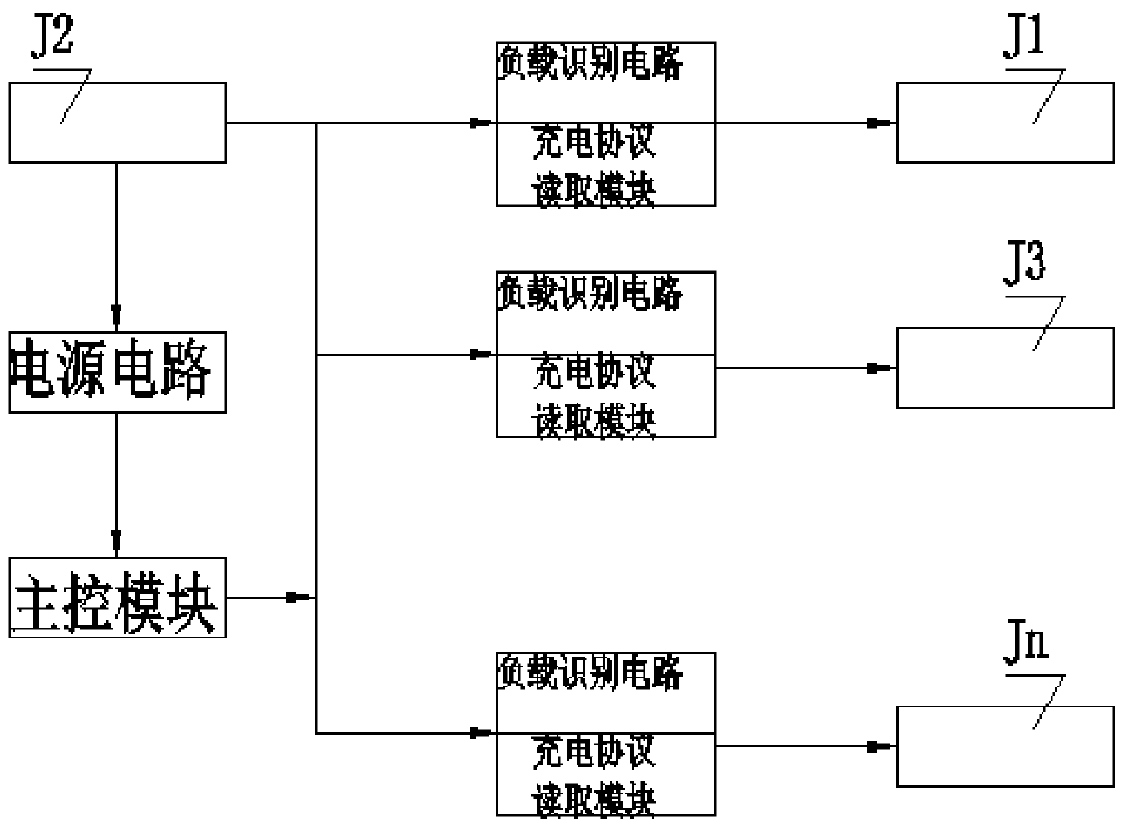
[0005] In order to solve the problem in the prior art that the charging wires cannot be quickly charged with multiple output interfaces in the case of one drag and many, the present invention provides a fast charging wire and a fast charging method that can effectively solve the above problems

Method used


Image

  • Multi-split quota distribution fast charging wire and fast charging method
  • Multi-split quota distribution fast charging wire and fast charging method
  • Multi-split quota distribution fast charging wire and fast charging method

Examples


specific Embodiment I

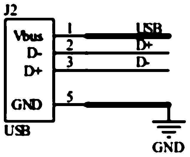
[0025] Specific embodiment I: the first USB output interface J1 is a Type-C interface; the second USB output interface J3 is a MicroUSB as an example for description.

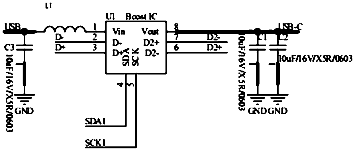
[0026] When the Type-C port detects that there is a load, it first collects the charging protocol of the load. At this time, the input power value is P. At this time, the MCU unit U4 controls the output power of the first protocol reading unit U1 to be P; when the MicroUSB port When the load is inserted, the MCU unit U4 detects the second load, and through the SDA1 port, SCK1 port, SDA2 port, and SCK2 port circuit, the two output powers are controlled to be 1 / 2P respectively, that is, the total input power is divided into two equal parts. .

[0027] There is no communication between any two output protocol circuits of this circuit. When a load is inserted, the input power P is equally divided. If there are n outputs in total, the output power is P / n.

[0028] Specifically, such as Figure 2-9 , a fast chargin...

specific Embodiment II

[0036] Specific embodiment II: the first USB output interface J1 is a Type-C interface; the second USB output interface J3 is a MicroUSB as an example for description.

[0037] When a load is connected to the Type-C interface, first the port labeled Load-C_DEL on the tenth resistor R10 will be pulled down. The protocol reading unit U1 communicates, and the first protocol reading unit U1 will identify the charging protocol and power P of the connected load through the D- and D+ ports. When it is confirmed that only one load is connected, the load is notified through the D2+ and D2- ports on the first protocol reading unit U1 that the maximum output power is P.

[0038] Then, when a new load is connected to the MicroUSB, the port with the network label Load-B_DEL corresponding to the ninth resistor R9 will recognize that there is a new load connected, and then read the SDA2 on the unit U2 through the second protocol , SCK2 port communicates with MCU unit U4. At this time, beca...


PUM


Abstract

The invention provides a multi-split quota distribution fast charging wire and a fast charging method. The multi-split quota distribution fast charging wire comprises an input interface connected witha power supply and a plurality of output interfaces used for being connected with loads. According to the technical scheme, a quota distribution circuit is arranged between the input interface and the output interface; the quota distribution circuit collects a charging protocol of a first load arranged on the output interface and then charges the load according to the charging protocol, wherein the charging power of the quota distribution circuit is P; and the charging power of the n loads which are subsequently connected with other output interfaces is P / (n+1). The multi-split quota distribution fast charging wire is simple in circuit structure, small in finished product size, convenient to carry and capable of achieving the purpose that the plurality of output interfaces can perform fast charging.

Description

technical field [0001] The invention belongs to the field of wire rods, and in particular relates to a one-to-many quota-allocated fast-charging wire and a fast-charging method. Background technique [0002] With the development of mobile phone charging technology, most of the current smartphones use fast charging solutions. We are familiar with Qualcomm QC fast charging, OPPO VOOC flash charging, Huawei SuperCharge fast charging and so on. [0003] For the fast charging mode, the current charging cable mainly has two commonly used methods: one-to-one output, the input and output of the cable have only one way, which can realize data transmission and fast charging, but the cable interface is single, and multiple cables are required Going out; the other is the commonly used one-drag multi-wire on the market, which is generally shielded for fast charging output. Whether it is a single output or multiple outputs, there is only a conventional power output. [0004] For one-to-m...

Claims


Application Information

Patent Timeline
Patent Type & Authority Applications(China)
IPC IPC(8): H02J7/00H01R13/66
CPCH01R13/665
Inventor 何世友桂登宇
Owner SHENZHEN BASEUS TECH CO LTD
Learn More