
A Power Supply Air Guide Cover Structure for Realizing Optionality

An air hood and power supply technology, which is applied to electrical components, electrical equipment housings/cabinets/drawers, chassis/boxes/drawer parts, etc. problems such as increased consumption

Active Publication Date: 2021-08-20
SUZHOU METABRAIN INTELLIGENT TECH CO LTD
View PDF0 Cites 0 Cited by
  • Summary
  • Abstract
  • Description
  • Claims
  • Application Information

AI Technical Summary

Problems solved by technology

[0003] With the improvement of server integration and density, the power consumption of the server also increases, and it is necessary to install multiple sets of power modules inside the server. The module components distribute the air flow reasonably, thus affecting the heat dissipation effect of the power module and even causing downtime

Method used


Image

  • A Power Supply Air Guide Cover Structure for Realizing Optionality
  • A Power Supply Air Guide Cover Structure for Realizing Optionality
  • A Power Supply Air Guide Cover Structure for Realizing Optionality

Examples


Embodiment 1

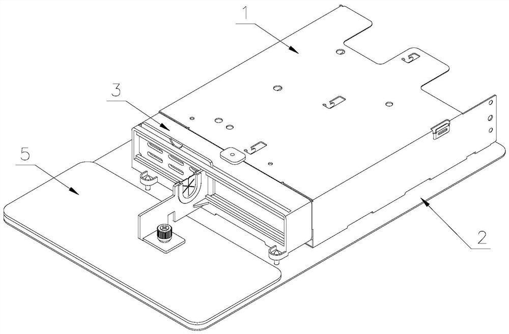
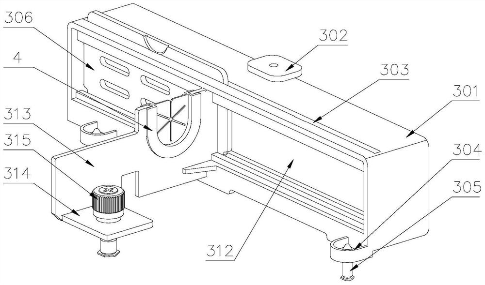
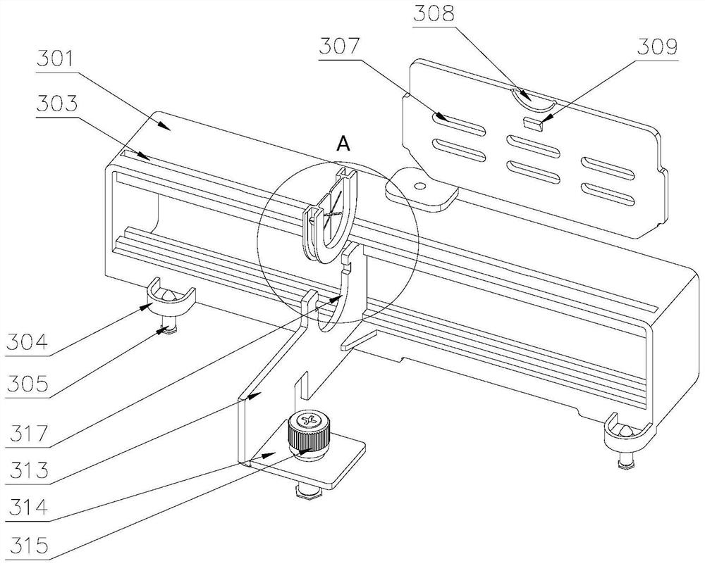
[0039] refer to Figure 1-3 , an optional power supply air guide structure, including a power supply bracket 1 and an air guide cover 3, the lower part of the power supply bracket 1 is installed on the chassis base 2, and the power supply module is installed inside the power supply bracket 1. The air guide cover 3 includes a main body 301 and a vertical plate 313. The main body 301 is provided with an air guide hole 312. One end of the upper part of the main body 301 is fixedly connected with the upper part of the power supply bracket 1 through a fixing plate 302, and the front part of the air guide cover 3 is fixed. On the power supply support 1, a vertical plate 313 is provided on one side of the middle part of the body 301, and a connecting plate 314 is provided on one side of the vertical plate 313, and a fastening screw 315 is provided on the connecting plate 314, and the fastening screw 315 is connected with the The chassis base 2 is threaded, and the tail of the air gui...

Embodiment 2

[0049] refer to Figure 7 , Figure 8 , the difference from Embodiment 1 is that the fixing device 309 includes a housing 320 disposed on the body 301 and a rear cover 321 disposed on one side of the housing 320 , and the housing 320 and the rear cover 321 are connected by several connecting columns 322 , the connecting column 322 on one side is fixedly equipped with a second catch 323, one side of the second catch 323 is provided with a buckle 324, and the end of the buckle 324 near the second catch 323 is provided with an arc buckle Groove 325, the upper part of the other side of the buckle plate 324 is provided with a step-connected third slot 327 and a fourth slot 328, the side of the buckle plate 324 is provided with a first torsion spring 326, and one end of the first torsion spring 326 Set on the lower part of the pinch plate 324, the other end of the first torsion spring 326 is set on the shell 320; one side of the pinch plate 324 is provided with a clamping plate 329...


PUM


Abstract

The invention discloses an optional power supply air guide cover structure, which includes a power supply bracket and an air guide cover. Vertical plate, with air guide holes in the body, one end of the upper part of the body is fixedly connected with the upper part of the power supply bracket through a fixing plate, a vertical plate is provided on one side of the middle part of the body, a connecting plate is provided on one side of the vertical plate, and fastening screws are provided on the connecting plate , the fastening screw is threadedly connected with the base of the chassis; there is a slot on the body, and a baffle is provided inside the slot, and the width of the baffle is equal to the width of the power module. In the present invention, a slot is provided on the air guide cover, and a baffle is provided inside the slot. When the power modules are in one group, the baffle is inserted on the other side of the power module. When the power modules are in two groups At this time, the baffle is removed to ensure the reasonable configuration of the air flow in the power module and the heat dissipation effect of the power module.

Description

technical field [0001] The invention belongs to the technical field of heat dissipation of server power supplies, and in particular relates to a structure of a power supply windshield for realizing selectability. Background technique [0002] In the era of big data, the Internet, communication and other industries have an increasing demand for data traffic, and the requirements for performance configuration in the server are getting higher and higher, and the integration and density are high. The cooling of the server is also a design requirement. For CPU , memory, hard disk, and power supply, etc., has long been a subject that the industry has been studying. [0003] With the improvement of server integration and density, the power consumption of the server also increases, and it is necessary to install multiple sets of power modules inside the server. The module components distribute the air flow reasonably, thus affecting the heat dissipation effect of the power module a...

Claims


Application Information

Patent Timeline
Patent Type & Authority Patents(China)
IPC IPC(8): H05K5/02
CPCH05K5/0213H05K5/0217H05K5/0247
Inventor 闫福寿周立明
Owner SUZHOU METABRAIN INTELLIGENT TECH CO LTD
Learn More