Spraying arm for cleaning machine and cleaning machine

A spray arm and washing machine technology, which is applied to household cleaning devices, tableware washing machines/washing machines, tableware washing machines/rinsing machine parts, etc., can solve the problem of reduced spray area, poor reliability, and inability to effectively spray Dead angle and other problems, to achieve the effect of increasing the spray area and the cleaning area

Active Publication Date: 2020-06-26
NINGBO FOTILE KITCHEN WARE CO LTD
View PDF9 Cites 2 Cited by
  • Summary
  • Abstract
  • Description
  • Claims
  • Application Information

AI Technical Summary

Problems solved by technology

This patent is provided with at least two auxiliary spray arms on the main spray arm, which can effectively expand the spray area, thereby improving the cleaning rate, but the auxiliary spray arms are completely rotated by the spray water flow from the water spray hole. When it does not move to the dead angle, the auxiliary spray arm and the main spray arm form the largest spray area. When it moves to the dead angle, the auxiliary spray arm rotates to deviate from the length direction of the main spray arm, and its spray area decreases instead. Unable to effectively spray dead angle, poor reliability

Method used


Image

  • Spraying arm for cleaning machine and cleaning machine
  • Spraying arm for cleaning machine and cleaning machine
  • Spraying arm for cleaning machine and cleaning machine

Examples


Embodiment 1

[0056] Such as Figure 1 to Figure 14 Shown is the first preferred embodiment of the present invention.

[0057] Such as Figure 9 with Figure 10 As shown, the washing machine of this embodiment includes a box body 5, a spray arm and a power assembly. The box body 5 has a washing cavity 5a with a hollow interior and an open top. The spray arm is horizontally rotatably arranged at a position adjacent to the bottom in the washing cavity 5a. The power assembly is arranged at the bottom of the box body 5 and at least partly located below.

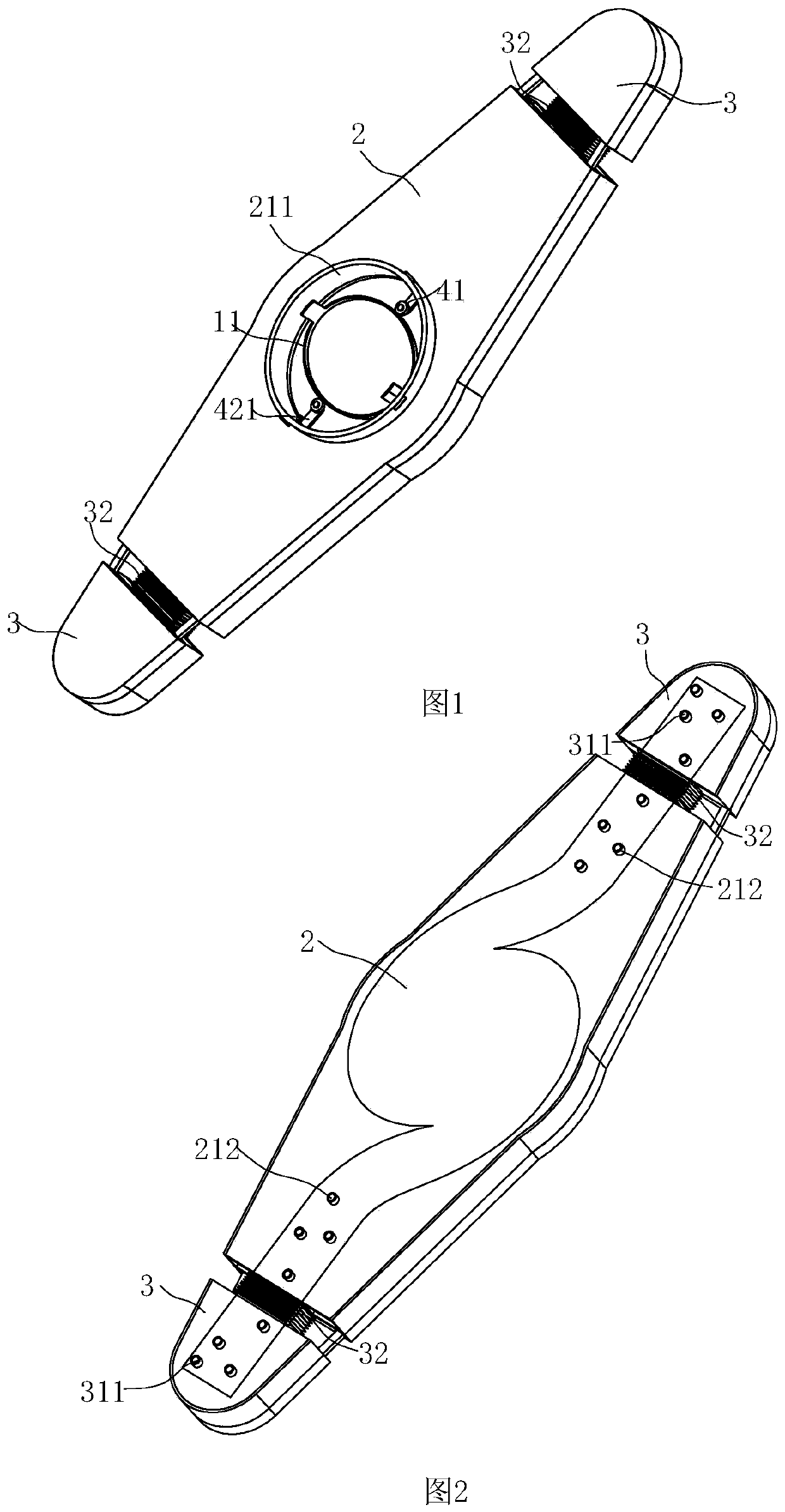
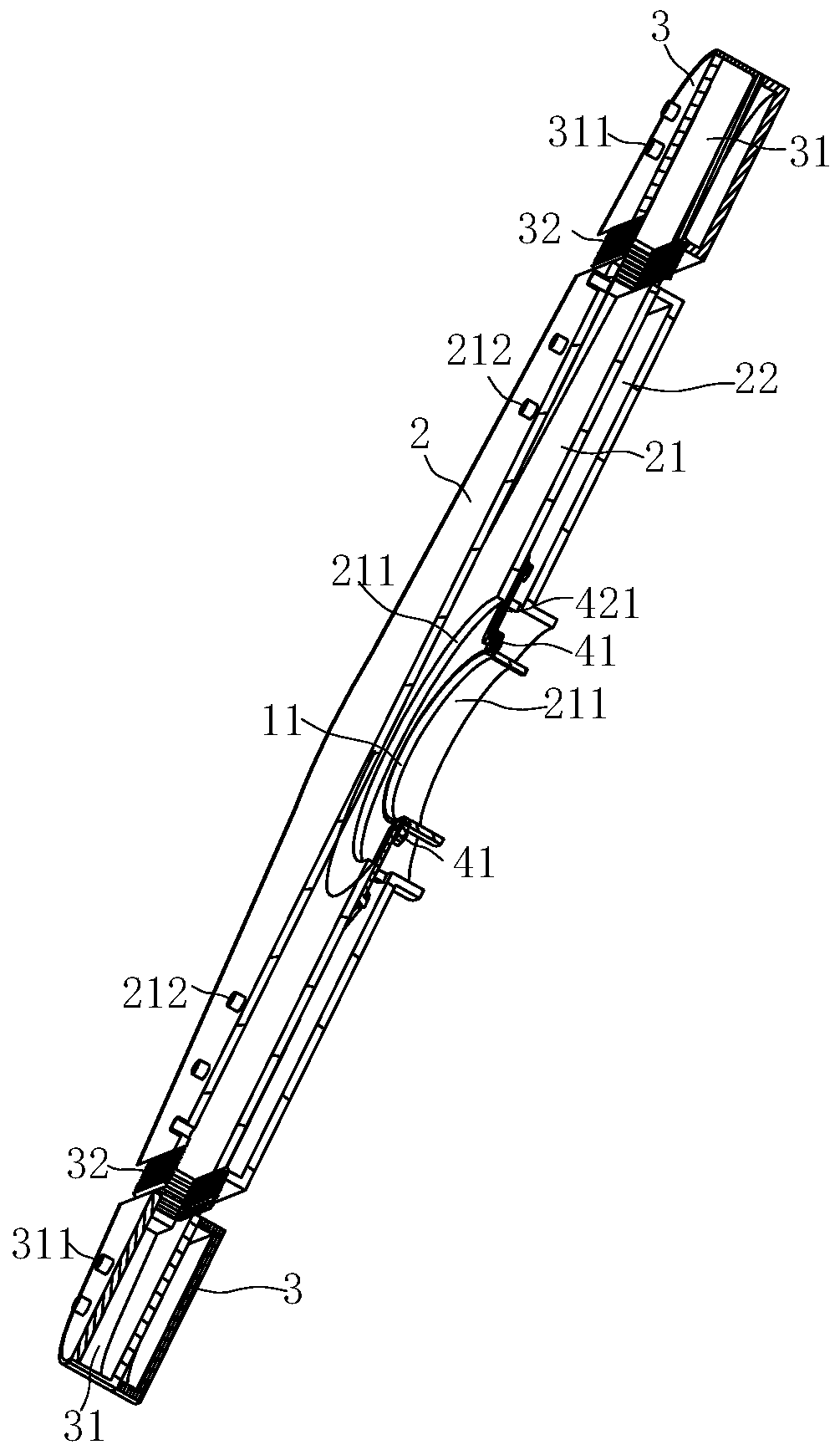
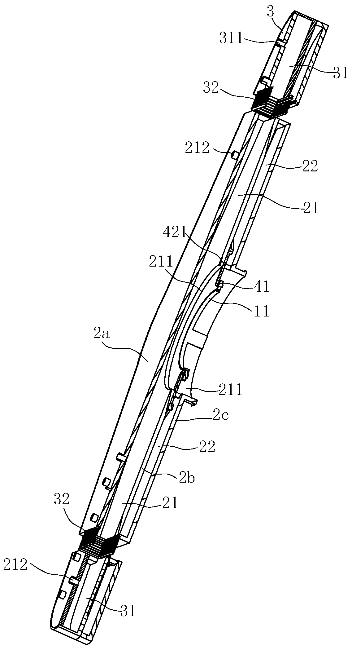
[0058] Such as Figure 1 to Figure 8 As shown, the spray arm used for the cleaning machine includes a main spray arm 2 , a secondary spray arm 3 , a linkage assembly and a fixing member fixedly connected to the bottom wall of the box body 5 .

[0059] Such as Figure 1 to Figure 8 As shown, the width of the main spray arm 2 gradually decreases from the center to both ends along the length direction, and the main spray arm 2 is arranged t...

Embodiment 2

[0067] Such as Figure 15 to Figure 17 Shown is the second preferred embodiment of the present invention.

[0068] The difference between this embodiment and the first embodiment above is only:

[0069] The ball 41 in the linkage assembly is matched with the connecting ring 11 in a different manner. Specifically, the connecting ring 11 has a slideway 112 extending along its circumference. The slideway 112 is an annular groove with an open top, and the ball 41 in the linkage assembly slides The position is limited in the slideway of the connecting ring 11, so that the ball 41 is limited on the connecting ring 11 along the circumferential movement of the connecting ring 11. For details, see Figure 15 to Figure 17 shown.


PUM


Abstract

The invention relates to a spraying arm for a cleaning machine and the cleaning machine. The spraying arm for the cleaning machine comprises: a main spraying arm, wherein a main flow channel is formedin the main spraying arm, and a water inlet channel for water to flow into the main flow channel is formed in the main spraying arm; an auxiliary spraying arm, wherein a sub-runner in fluid communication with the main runner is arranged in the auxiliary spraying arm, and spraying holes are formed in at least one of the auxiliary spraying arm and the main spraying arm, a cavity which is not communicated with the main flow channel and the water inlet channel is formed in the main spraying arm, the auxiliary spraying arm can be arranged on the main spraying arm in a manner of moving back and forth in the length direction of the main spraying arm,the spraying arm further comprises a fixing piece located in the water inlet channel, and the main spraying arm is arranged to rotate around the fixing piece; and a linkage assembly which is at least partially located in the cavity and used for enabling the auxiliary spraying arm to move back and forth in the length direction of the main sprayingarm, wherein the output end of the linkage assembly is in transmission connection with the auxiliary spraying arm, and the input end of the linkage assembly is arranged to be capable of rotating around the fixing piece. The spraying arm can reliably stretch out and draw back to increase the cleaning area.

Description

technical field [0001] The invention relates to the technical field of dishwashers, and specifically relates to a spray arm for a washing machine and a washing machine. Background technique [0002] Along with improving day by day of people's living standard, dishwasher more and more enters family as a kind of kitchen appliance product. Dishwashers currently on the market are generally divided into three types: table type, cabinet type, and tank type. Among them, the table type dishwasher is an integral independent structure, which is generally placed on the table for use; , but needs to be embedded in the kitchen cabinet for use; the sink dishwasher is combined with the water tank and is generally installed in the kitchen cabinet for use. [0003] The above-mentioned various forms of dishwashers generally use a water pump to lift water and spray it to the dishes in the cleaning space so as to achieve the cleaning effect. For example, the Chinese utility model patent "A Sp...

Claims


Application Information

Patent Timeline
IPC IPC(8): A47L15/22A47L15/42
CPCA47L15/22A47L15/428
Inventor 潘嘉威
Owner NINGBO FOTILE KITCHEN WARE CO LTD
Why Eureka
Try Eureka