A kind of knee spacer and preparation method thereof

A technology for knee joints and placeholders, applied in the direction of knee joints, elbow joints, joint implants, etc., can solve the problems of increased difficulty of revision, scar hyperplasia, and large resistance to movement, achieving reliable appearance and structure, The effect of large joint mobility and low interface wear

Active Publication Date: 2022-04-12
XIANGYA HOSPITAL CENT SOUTH UNIV
View PDF0 Cites 0 Cited by
  • Summary
  • Abstract
  • Description
  • Claims
  • Application Information

AI Technical Summary

Problems solved by technology

[0004] However, this traditional method of making placeholders has many problems and disadvantages: (1) all handwork and different experiences; (2) size and shape are difficult to fit; Friction or even cutting occurs between the contacting bone surfaces; (4) The flexion and extension of the knee joint cannot be smoothly completed between the spacer on the femoral side of the knee joint and the spacer on the tibial side of the knee joint. The wear between the spacers is large, and the patient's function is poor after operation; (5) The spacer often rubs and cuts the bone after surgery, so the patient often feels pain after the operation, and the patient's function is poor after the operation, and these symptoms will be in the absence of need. (6) The placeholder rubs and cuts the bone for a long time, so when the revision operation is performed after the 3-6 month of the exclusion operation, a large amount of bone wear and loss often occurs, and a large number of scars Hyperplasia and other sequelae greatly increase the difficulty of revision

Method used


Image

  • A kind of knee spacer and preparation method thereof
  • A kind of knee spacer and preparation method thereof
  • A kind of knee spacer and preparation method thereof

Examples


Embodiment 1

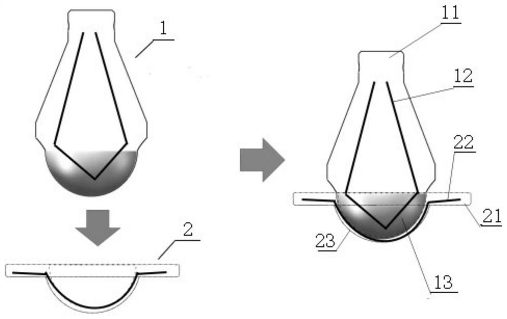
[0058] see Figure 1-12 , the present embodiment provides a knee spacer, including the Spacer femoral side 1;

[0059] The Spacer femoral side 1 includes a first bone cement body part 11, a first Kirschner wire 12 and a first metal prosthesis contact part 13;

[0060] The first bone cement main body 11 includes a first cylinder 111, the lower end of the first cylinder 111 is connected with a first circular platform 112 with a narrow top and a wide bottom, and a second cylindrical body 113 is connected with the lower end of the first circular platform 112 , the lower end of the second cylinder 113 is connected with a second circular platform 114 with a wide top and a narrow bottom;

[0061] The first metal prosthesis contact part 13 is a semi-spherical structure with the spherical surface facing downwards, and the upper surface of the semi-spherical structure is connected to the lower end of the second round platform 114;

[0062] The first Kirschner wire 12 is located in the m...

Embodiment 2

[0072] This embodiment provides a method for preparing a knee joint spacer, comprising the following steps:

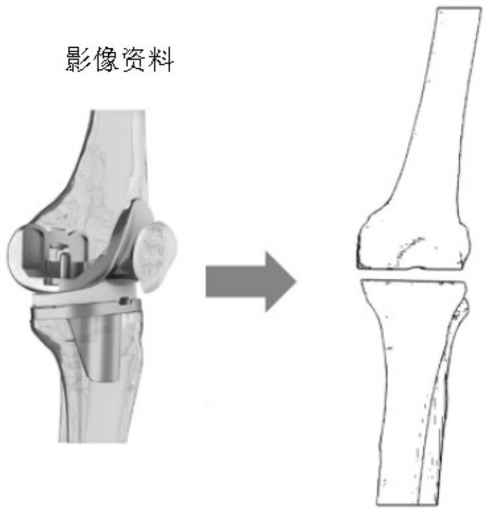
[0073] Step 1, obtain the image data of the patient's knee joint through the patient's X-ray or CT;

[0074] Step 2, converting the image data into editable three-dimensional data of the knee joint through a computer;

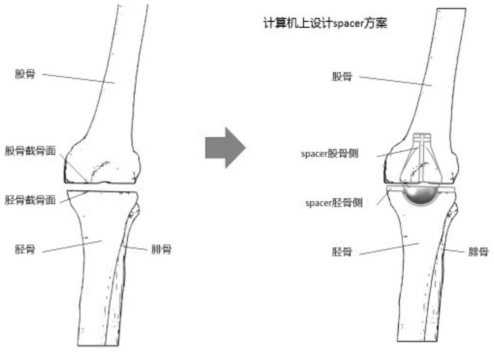
[0075] Step 3, determine the osteotomy scheme on the computer according to the three-dimensional data of the knee joint;

[0076] Step 4, formulate Spacer femoral side 1 and Spacer tibial side 2 plans on the computer;

[0077] Step 5, according to the Spacer femoral side 2 and Spacer tibial side 2 plans, design and determine the femoral side medullary canal reamer and tibial side medullary canal reamer;

[0078] Step 6: Design the specific structures of Spacer femoral side 1 and Spacer tibial side 2 according to the femoral and tibial canal rasp scheme;

[0079] Step 7, according to the specific structure of the designed Spacer femoral side 1 and Spa...


PUM


Abstract

A knee joint spacer, comprising a Spacer femoral side and a Spacer tibial side; the Spacer femoral side includes a first bone cement main body, a first Kirschner wire, and a first metal prosthesis contact portion; the first metal prosthesis contact The upper surface of the part is connected with the lower end of the first bone cement main part; the first Kirschner wire is arranged in the middle part of the first bone cement main part and the first metal prosthesis contact part; the Spacer tibial side includes the second bone cement main body part, the second Kirschner wire and the second metal prosthesis contact part, the upper end of the second metal prosthesis contact part is connected with the lower end of the second bone cement main part, and the second Kirschner wire is arranged on the second bone cement main body part and the inside of the second metal prosthesis contact part, the Spacer tibial side is also provided with a cavity structure for placing the first metal prosthesis contact part; the invention also discloses a preparation method of the knee joint spacer .

Description

technical field [0001] The invention relates to the technical field of surgical implants, in particular to a knee joint spacer and a preparation method thereof. Background technique [0002] At present, when postoperative periprosthetic infection occurs in artificial joint replacement surgery, or when there is serious infection in the joint itself that needs to be solved by artificial joint surgery, joint exclusion surgery is generally used clinically to control infection. Such patients generally undergo about 3- The joint infection was healed after June's evacuation operation, and then artificial joint replacement was performed again. [0003] In joint exclusion surgery, the previous joint prosthesis is usually removed first. At this time, there will be a huge cavity inside the joint that is consistent with the shape of the prosthesis, and some germs and infectious substances will remain around this cavity more or less , so clinically doctors usually use antibiotic-contain...

Claims


Application Information

Patent Timeline
Patent Type & Authority Patents(China)
IPC IPC(8): A61F2/38A61F2/30
CPCA61F2/30942A61F2/3859A61F2/389A61F2/30749A61F2002/30024
Inventor 钟达王成功汪龙
Owner XIANGYA HOSPITAL CENT SOUTH UNIV
Why Eureka
Try Eureka