Electric multifunctional equipment pin detacher
A technology of multi-functional equipment and pin remover, which is applied to hand-held tools, manufacturing tools, etc., can solve the problems of no threaded shaft pin and no dismantling cotter pin, etc., and achieve the effect of ensuring the support area
- Summary
- Abstract
- Description
- Claims
- Application Information
AI Technical Summary
Problems solved by technology
Method used
Image
Examples
Embodiment 1
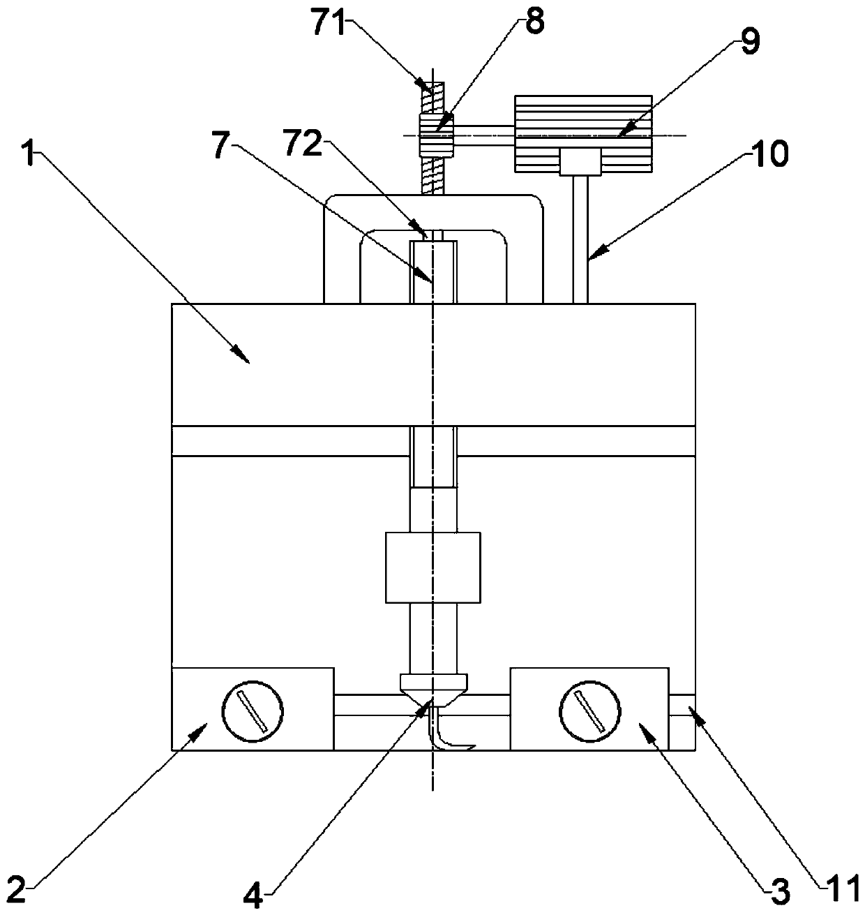
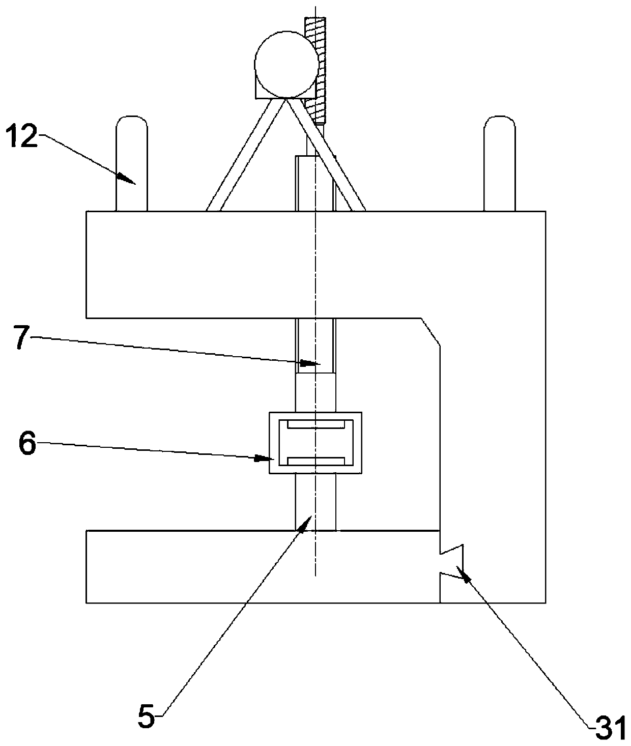
[0026] The power multi-function device debonder described in the embodiment of the present invention, such as figure 1 and figure 2 As shown, it includes: a device body 1 , a left magnetic base 2 , a right magnetic base 3 , a pin pulling assembly 4 , a lower rod 5 , a connecting piece 6 , an upper rod 7 , a worm gear 8 and a motor 9 . The device body 1 has a vertical part, the upper end of the vertical part extends laterally out of a horizontal part, the vertical part is provided with a penetrating dovetail groove 11 at the lower part of the same side with the extended horizontal part, the left magnetic base 2 and the right Dovetail plugs 31 corresponding to the dovetail slots 11 are respectively provided on the same side of the magnetic base 3 . The left magnetic base 2 and the right magnetic base 3 can be horizontally slidably adjusted along the dovetail groove 11 of the device body 1 to adapt to the tooling planes of various dismantling objects and further ensure the supp...
Embodiment 2
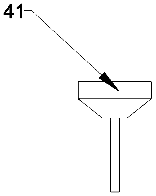
[0031] Based on the technical solution of the first embodiment, in this embodiment, the pin-pulling assembly 4 is replaced with a punching-out assembly 41 for impacting the pins outward, and its structure is as follows: image 3 As shown, the material of the punching assembly is 45 steel.
[0032]When using the technical solution of the present invention, the operator firstly adjusts the gap distance between the left magnetic base 2 and the right magnetic base 3, and places a mechanism equipped with a shaft pin, such as a knife gate connecting rod, on the left magnetic base 2 and the right magnetic base 3. on the magnetic base 3; secondly, align the shaft pin of the mechanism with the head of the punching pin assembly 41; then start the motor 9 to rotate counterclockwise, without manual force, the shaft pin can be removed, and the removal efficiency of the shaft pin is greatly improved .
PUM
 Abstract
Description
Claims
Application Information
 - R&D
- Intellectual Property
- Life Sciences
- Materials
- Tech Scout
- Unparalleled Data Quality
- Higher Quality Content
- 60% Fewer Hallucinations
Browse by: Latest US Patents, China's latest patents, Technical Efficacy Thesaurus, Application Domain, Technology Topic, Popular Technical Reports.
© 2025 PatSnap. All rights reserved.Legal|Privacy policy|Modern Slavery Act Transparency Statement|Sitemap|About US| Contact US: help@patsnap.com


