
Automatic powder coating equipment

A powder-coating and automatic technology, applied in the direction of coating, the device for coating liquid on the surface, etc., can solve the problems of low work efficiency, labor consumption of workers, uneven application of tablet lubricant, etc., to achieve high work efficiency, Simple smear work, even smear effect

Pending Publication Date: 2020-06-30
FOSHAN IROBOT AUTOMATIC
View PDF0 Cites 5 Cited by
  • Summary
  • Abstract
  • Description
  • Claims
  • Application Information

AI Technical Summary

Problems solved by technology

The existing hardware container lubrication treatment method is generally to manually apply lubricant to the outer surface of the metal sheet or pot liner one by one, which consumes a lot of labor for workers, and the work efficiency is low, and uneven application of lubricant to the sheet will also occur. The situation, the workpiece processing mode is not ideal

Method used


Image

  • Automatic powder coating equipment
  • Automatic powder coating equipment
  • Automatic powder coating equipment

Examples


Embodiment 1

[0026] The technical scheme of the present invention is illustrated below in conjunction with accompanying drawing:

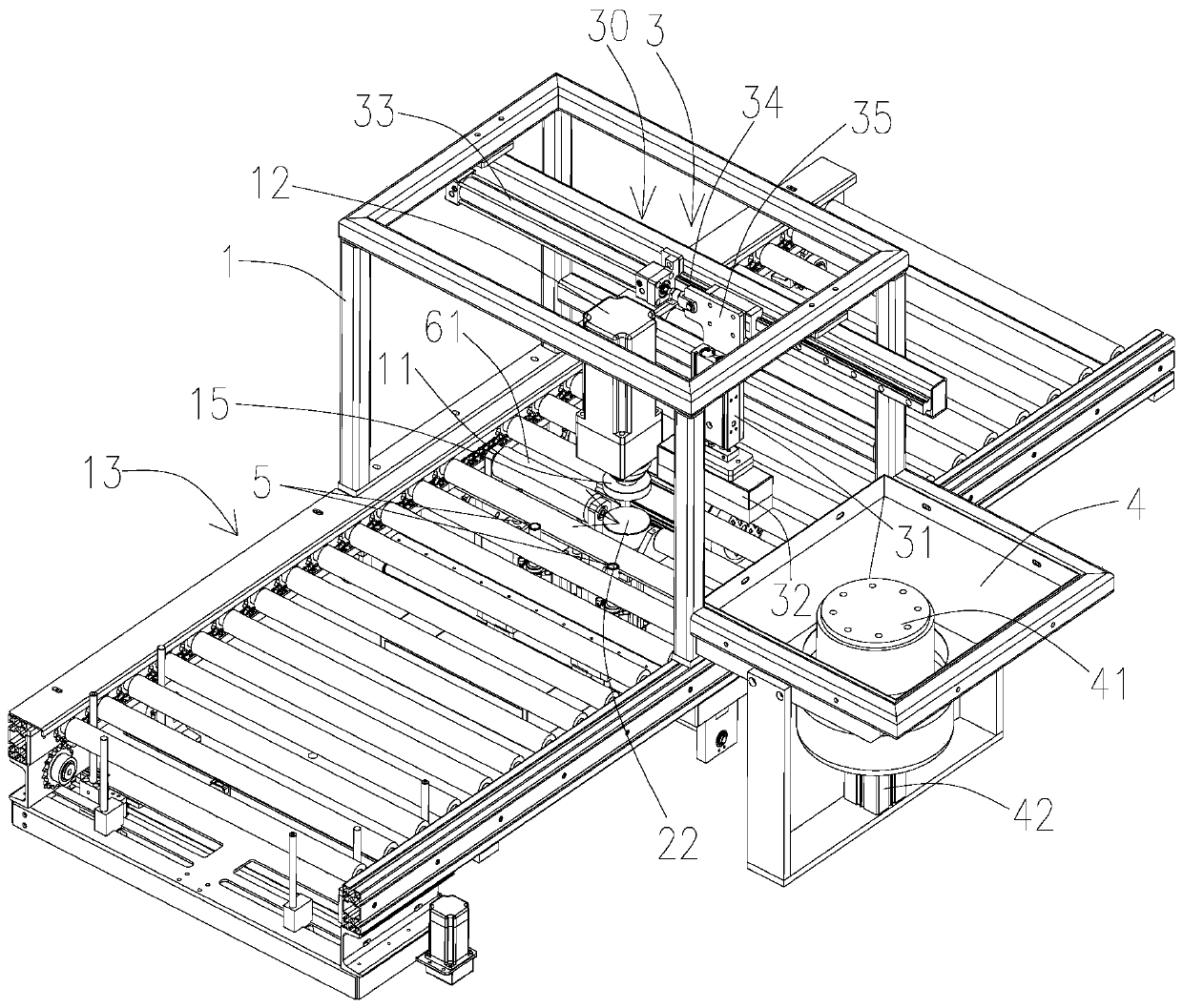
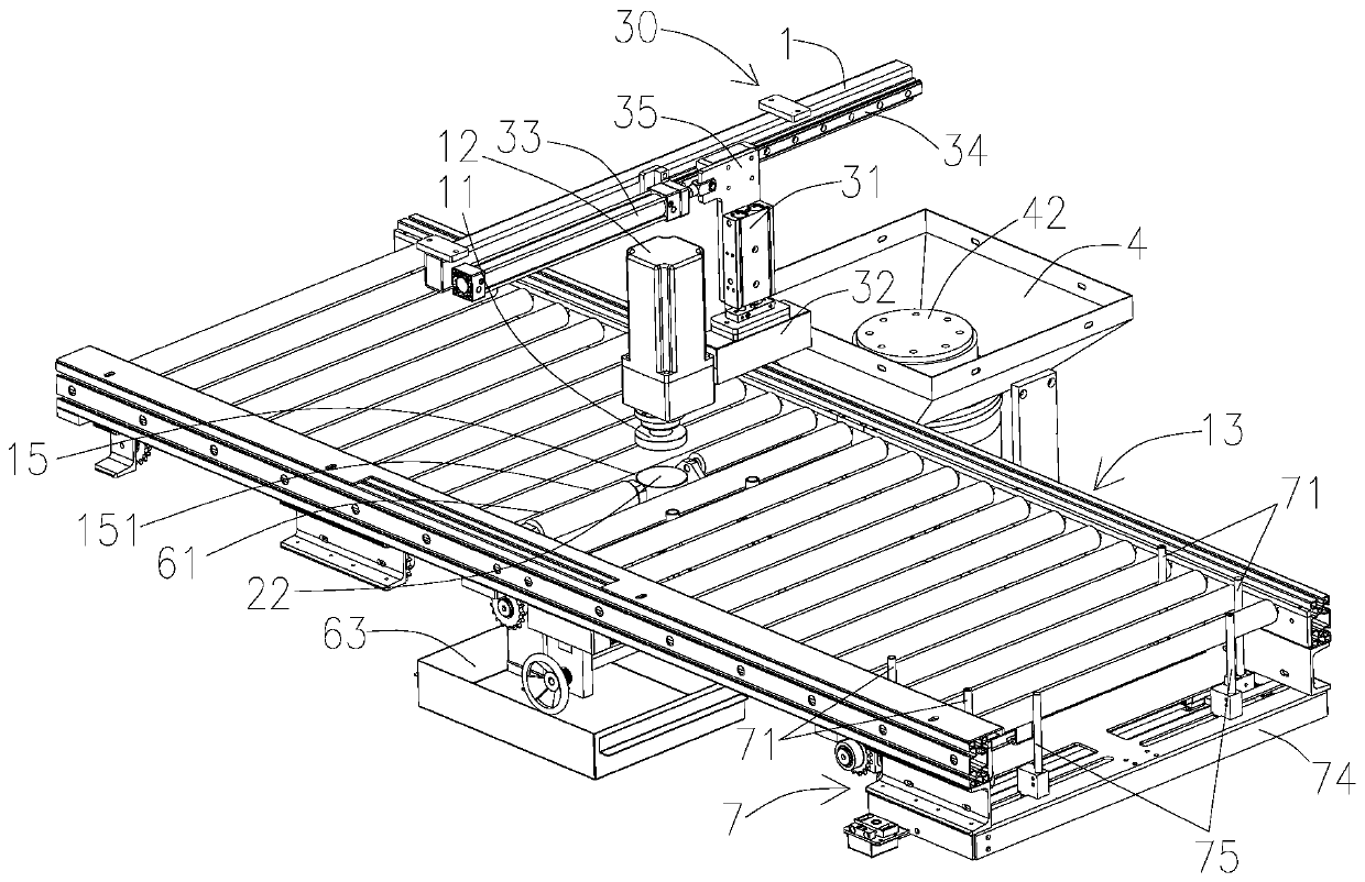
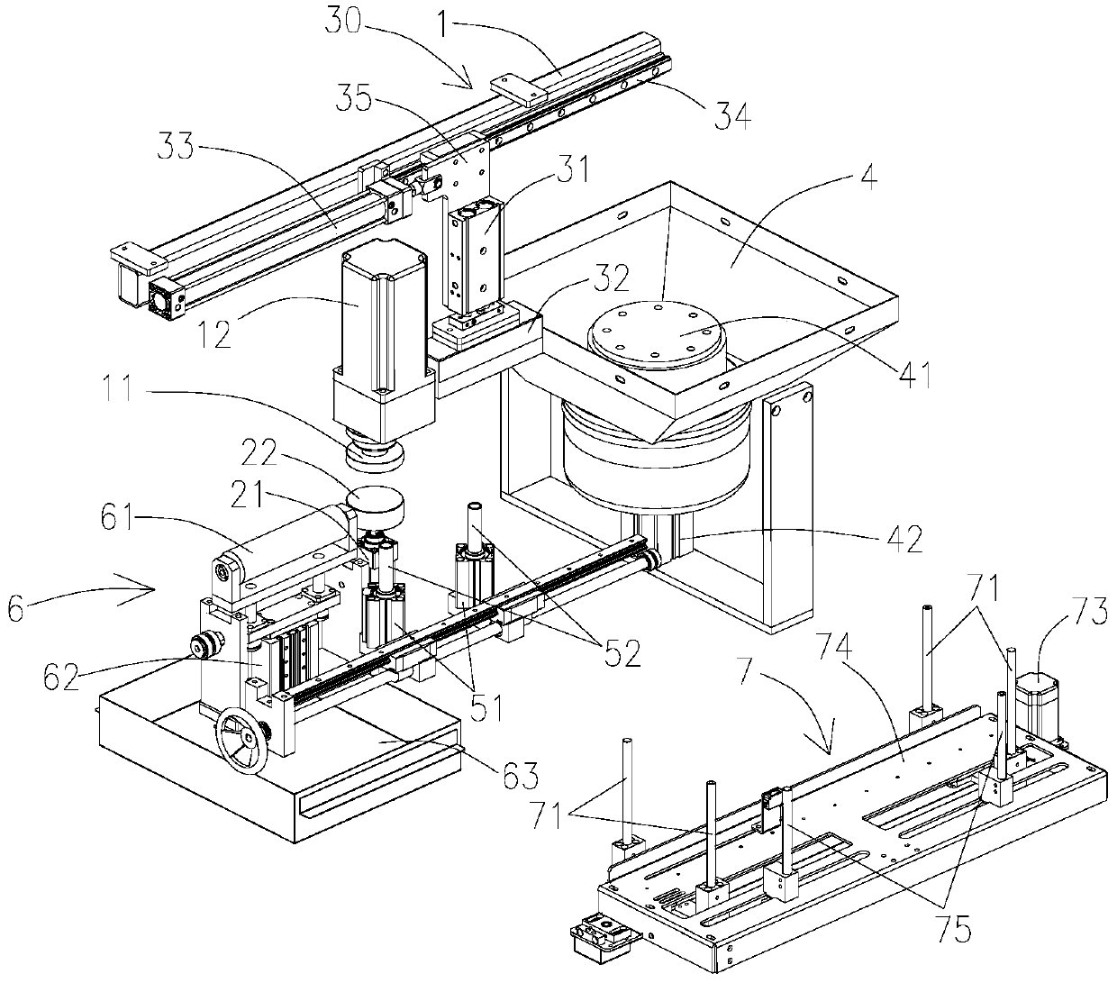
[0027] see Figure 1 to Figure 4 , the automatic powder coating equipment of the present invention comprises: a frame 1; and a rotating pallet 22 supporting workpieces; a rotating fixture 11 that fixes the work on the rotating pallet 22; driving the rotating fixture 11 or the rotating pallet 22 Rotating workpiece driving device 12; at least one powder coating mechanism 3, said powder coating mechanism 3 includes: a powder bin 4 loaded with lubricating powder; a powder brushing part 32 that takes lubricating powder from the powder bin 4 and smears it on the outer surface of the workpiece; The transfer device 30 that drives the powder brushing part 32 to move between the powder bin 4 and the powder brushing position close to the rotary pallet 22; the powder coating driver 31 that connects the powder brushing part 32 and the transfer device; when in the powder bru...

Embodiment 2

[0037] see Figure 5 to Figure 7 , The main difference between this embodiment and Embodiment 1 is that the powder coating mechanism is provided with two, respectively the first powder coating mechanism 3 mechanism and the second powder coating mechanism 8, the first powder coating mechanism 3 mechanism and the second powder coating mechanism The 8 mechanisms of the two powder coating machines are each equipped with an independent powder bin 4. The first powder coating machine 3 mechanism is set in the same way as the powder coating mechanism in Embodiment 1, and the second powder coating machine 8 mechanism replaces the powder coating mechanism. The oil mechanism 6 is arranged on the lower side of the workpiece conveying mechanism 13, and the workpiece conveying mechanism 13 is provided with a second avoidance opening 151 corresponding to the second powder coating mechanism 8, and the second avoidance opening 151 is arranged on the side of the rotary pallet 22 part, it is con...

Embodiment 3

[0042] see Figure 8, the automatic powder coating equipment of this embodiment is used for the second stretching of the pot liner for lubrication treatment, the outer surface of the pot liner needs to be powder coated, and the automatic powder coating method of manual feeding is adopted, Therefore, there is no need to set up a workpiece conveying mechanism 13. The main difference between this embodiment and Embodiment 1 is that the rotating platform 22 is provided with a positioning portion 111 that matches the opening of the pot liner, and the rotating fixing device 11 is located on the On the upper side of the rotating platform 22, the workpiece driving device 12 drives the rotating platform 22 to rotate, and the rotating fixing device 11 relatively drives the rotating supporting platform 22 to rise or fall by the vertical driving device 21. The rotating fixing device 11 is rotatably connected with the vertical driving device 21, and the vertical driving device 21 is prefer...


PUM


Abstract

The invention relates to automatic powder coating equipment which comprises a rack, a rotary supporting table, a rotary fixing device used for fixing a workpiece to the rotary supporting table, a workpiece driving device and a powder coating mechanism. The powder coating mechanism comprises a powder bin, a powder coating piece used for taking lubricating powder from the powder bin and smearing thelubricating powder on the outer surface of the workpiece, a transferring device used for driving the powder coating piece to move between the powder bin and the powder coating position close to the rotary supporting table and a powder coating driver connected with the powder coating piece and the transferring device; and at the powder coating position, the powder coating driver drives the powdercoating piece to be in contact with the rotating workpiece to coat the lubricating powder on the surface of the workpiece. Compared with the prior art, according to the automatic powder coating equipment, the workpiece is fixedly arranged through cooperation of the rotary fixing device and the rotary supporting table, the workpiece driving device drives the workpiece to rotate, the powder coatingpiece coats the outer surface of the workpiece with the lubricating powder in the relative circumferential direction, automatic lubricating agent coating of the workpiece is achieved, a traditional manual coating mode is replaced, the working efficiency is high, the coating working mode is simple, and the coating effect is more uniform.

Description

technical field [0001] The invention belongs to the technical field of hardware processing, and in particular relates to automatic powder coating equipment. Background technique [0002] During the processing of hardware containers (such as pot liners), due to material and process limitations of some products, the metal sheet needs to be stamped several times before it can be formed, and the surface of the metal sheet needs to be lubricated before each stamping process Treatment, such as applying lubricant; avoiding the deformation of the outer surface of the metal sheet during the primary stamping or the secondary stamping of the pot liner will cause friction loss to the inner wall of the stamping die, so as to ensure reliable processing of the product. The existing lubricating treatment method for hardware containers is generally to apply lubricant to the outer surface of the metal sheet or pot liner one by one manually, which consumes a lot of labor and the work efficienc...

Claims


Application Information

Patent Timeline
Patent Type & Authority Applications(China)
IPC IPC(8): B05C19/00B05C13/02B05C1/02B05C19/06
CPCB05C1/02B05C13/02B05C19/00B05C19/008B05C19/06
Inventor 农百乐潘扬树
Owner FOSHAN IROBOT AUTOMATIC
Learn More