Positioning and lifting system for large structural member

A technology of large structural parts and lifting plates, which is applied in the direction of lifting devices and safety devices of lifting equipment, etc., can solve the problems of lifting device failure, dangerous working process, waste of time and manpower, etc., to ensure safe lifting and improve safety resistance, the effect of preventing failure

Active Publication Date: 2020-06-30
SHENYANG INST OF AUTOMATION - CHINESE ACAD OF SCI
View PDF11 Cites 7 Cited by
  • Summary
  • Abstract
  • Description
  • Claims
  • Application Information

AI Technical Summary

Problems solved by technology

[0002] At present, the assembly of large structural parts is completed on a fixed platform or tooling. The transportation of structural parts is generally completed by hoisting, but this method not only wastes time and manpower, but also the working process is relatively dangerous, and it is impossible Meet the requirements of intelligent manufacturing. For example, in the assembly process of AGV (Automatic Guided Transport Vehicle) and other devices carrying workpieces, the existing bench or tooling cannot realize the in-place detection of AGV and other transportation carriers, and cannot automatically implement follow-up actions. These At present, human manipulation is required, which poses great difficulties to the beat control and quality control of the entire production line. In addition, due to the large volume and weight of large structural parts, accidents are prone to occur in actual production, causing the lifting device to fail and cause danger.

Method used


Image

  • Positioning and lifting system for large structural member
  • Positioning and lifting system for large structural member
  • Positioning and lifting system for large structural member

Examples


Embodiment Construction

[0028] The present invention will be described in further detail below in conjunction with the accompanying drawings.

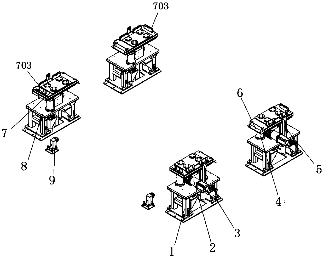
[0029] like Figure 1-8 As shown, the present invention includes a plurality of lifting devices and a plurality of limiting devices 9, such as figure 1 As shown, a plurality of lifting devices are arranged symmetrically on both sides of the lifting station, and the limiting device 9 is provided on one side of the lifting station.

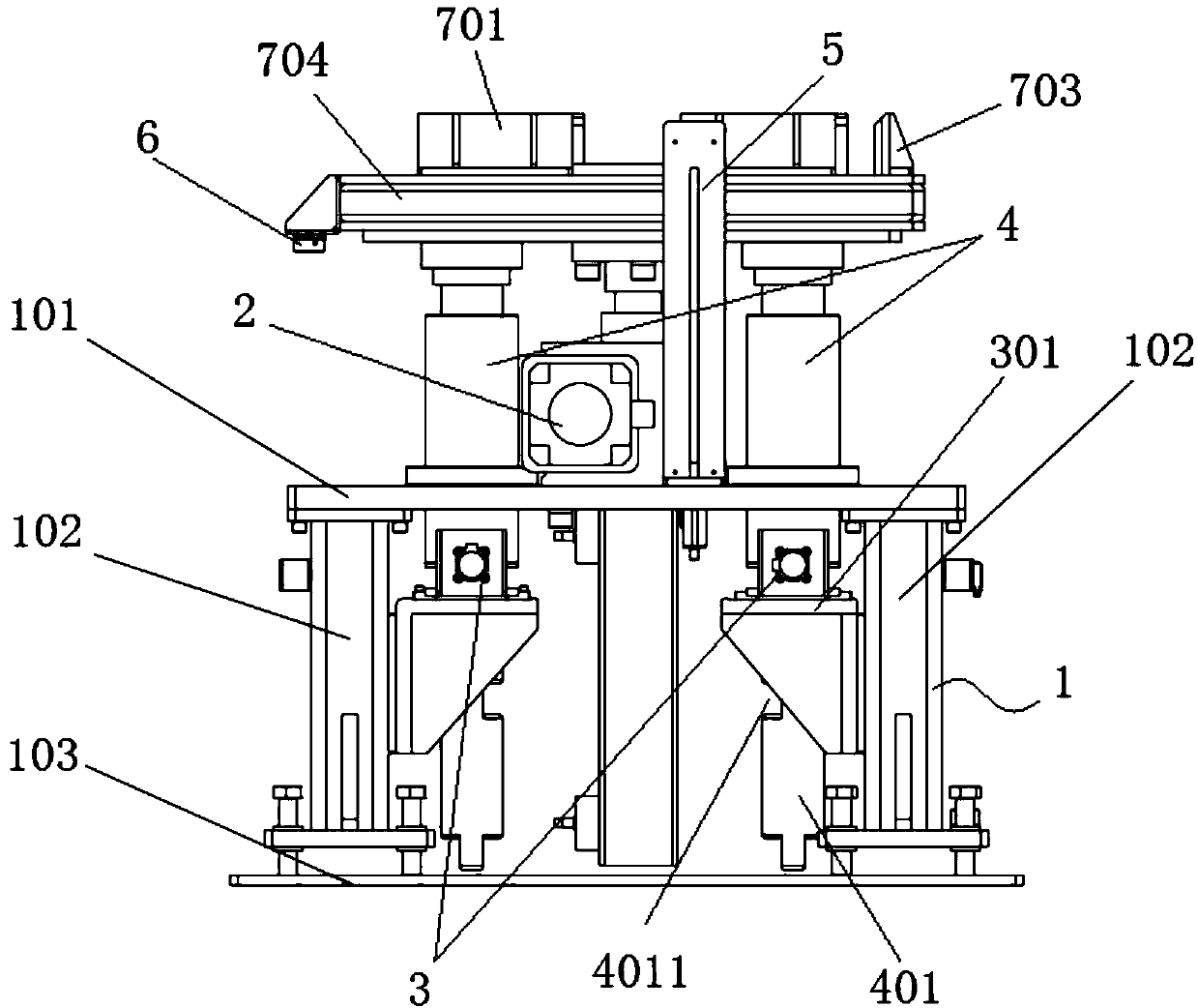
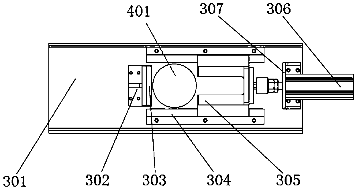
[0030] like Figure 2-6 As shown, the lifting device includes a lifting plate assembly 7, a screw jack 2, a guide mechanism 4, an anti-fall mechanism 3 and a base 1, the upper side of the base 1 is provided with a support plate 101, and the screw jack 2 and the guide Mechanisms 4 are installed on the support plate 101, the lifting plate assembly 7 is driven up and down by the screw jack 2, the guide mechanism 4 is provided with a movable guide column 401, and the lower side of the lifting plate assembly 7 It is fixedly connected...


PUM


Abstract

The invention relates to the technical field of assembly, in particular to a positioning and lifting system for a large structural member. The positioning and lifting system for the large structural member comprises lifting devices and a limiting device, wherein the lifting devices comprise lifting plate assemblies, spiral elevators, guide mechanisms, falling prevention mechanisms and bases, the spiral elevators and the guide mechanisms are both arranged on the bases, the lifting plate assemblies are driven to lift through the spiral elevators, the guide mechanisms are provided with guide columns, the lower sides of the lifting plate assemblies and the upper ends of the guide columns are fixedly connected, the lower ends of the guide columns extend into the bases, the falling prevention mechanisms are arranged in the bases, the falling prevention mechanisms correspond to the guide mechanisms one by one, the falling prevention mechanisms comprise limiting sliding blocks and air cylinders, the lower parts of the guide columns are provided with notches, when the lifting plate assemblies are lifted in place, the limiting sliding blocks are driven by the air cylinders to move and be clamped in the notches on the corresponding guide columns, and lifting detection assemblies are arranged on the base. An in-place detection assembly is provided on either lifting device. The positioningand lifting system for the large structural member ensures the safety and improves the automation level and the working efficiency of a production line.

Description

technical field [0001] The invention relates to the technical field of assembly, in particular to a positioning and lifting system for large structural parts. Background technique [0002] At present, the assembly of large structural parts is completed on a fixed platform or tooling. The transportation of structural parts is generally completed by hoisting, but this method not only wastes time and manpower, but also the working process is relatively dangerous, and it is impossible Meet the requirements of intelligent manufacturing. For example, in the assembly process of AGV (Automatic Guided Transport Vehicle) and other devices carrying workpieces, the existing bench or tooling cannot realize the in-place detection of AGV and other transportation carriers, and cannot automatically implement follow-up actions. These At present, human manipulation is required, which poses great difficulties to the beat control and quality control of the entire production line. In addition, du...

Claims


Application Information

Patent Timeline
Patent Type & Authority Applications(China)
IPC IPC(8): B66F3/46B66F17/00
CPCB66F3/46B66F17/006
Inventor 杜劲松刘博王晓龙郭锐尹健谭广超
Owner SHENYANG INST OF AUTOMATION - CHINESE ACAD OF SCI
Why Eureka
Try Eureka