
Energy-saving door and window drainage anti-mosquito structure and mounting method

A technology for anti-mosquito, doors and windows, which is applied to door/window protection devices, insect-proof, windows/doors, etc. It can solve the problems of troublesome rubber stoppers, aging rubber stoppers, easy to fall off, etc., and achieves convenient installation, easy access, The effect of simple overall structure

Pending Publication Date: 2020-06-30
周志高
View PDF0 Cites 0 Cited by
  • Summary
  • Abstract
  • Description
  • Claims
  • Application Information

AI Technical Summary

Problems solved by technology

[0002] At present, the existing windows all adopt the frame and pull-out window structure. This structure has the characteristics of convenient installation and wide applicability. It is widely used in urban high-rise buildings, factory buildings and residential areas, and self-built houses in rural areas. The glass window can be opened and closed by using the handle. The existing technology is that most door and window structures will leave two small holes at the bottom of the frame. When it rains heavily in high-rise buildings, this type of door and window will have rainwater leaking into the frame. In general, the function of this hole is to use the hole to effectively discharge the water leaking into the frame and prevent the generation of accumulated water. However, if it is a normally open structure, mosquitoes and other organisms outside can enter the room through this hole , cannot effectively prevent mosquitoes. Therefore, a rubber stopper or other things are usually installed at the frame to temporarily block it. This structure also has two disadvantages: 1. The rubber stopper is easy to fall off after a long time; 2. If there is rain or accumulated It is cumbersome to manually take out the rubber stopper when the water stays on the frame. Therefore, a structure that can prevent mosquitoes and drain water is needed to solve the existing technical problems

Method used


Image

  • Energy-saving door and window drainage anti-mosquito structure and mounting method
  • Energy-saving door and window drainage anti-mosquito structure and mounting method
  • Energy-saving door and window drainage anti-mosquito structure and mounting method

Examples


Embodiment Construction

[0024] The preferred embodiments of the present invention will be described in detail below in conjunction with the accompanying drawings, so that the advantages and features of the present invention can be more easily understood by those skilled in the art, so as to define the protection scope of the present invention more clearly.

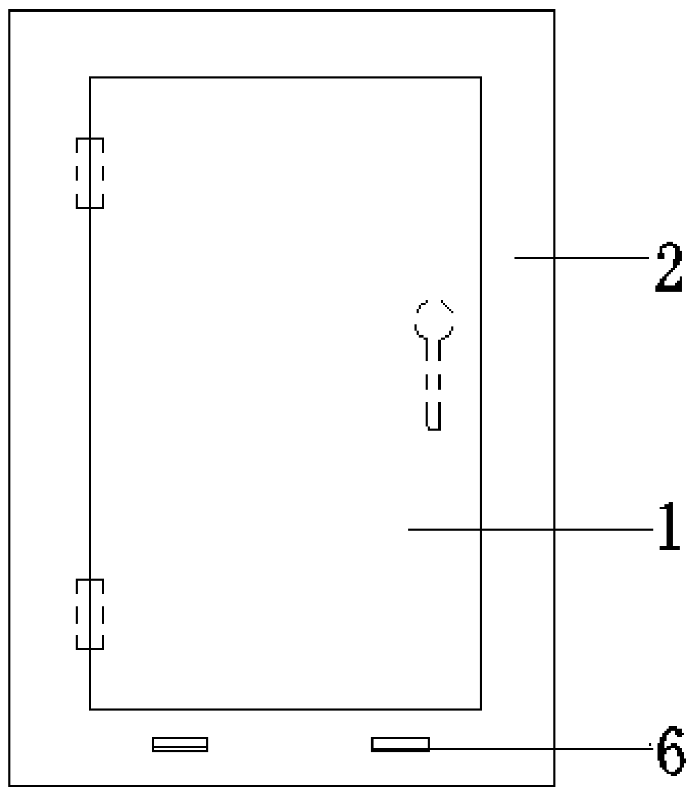
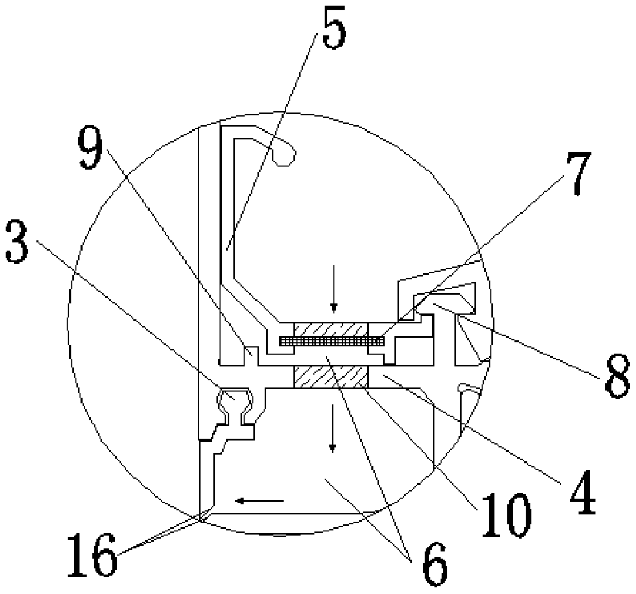
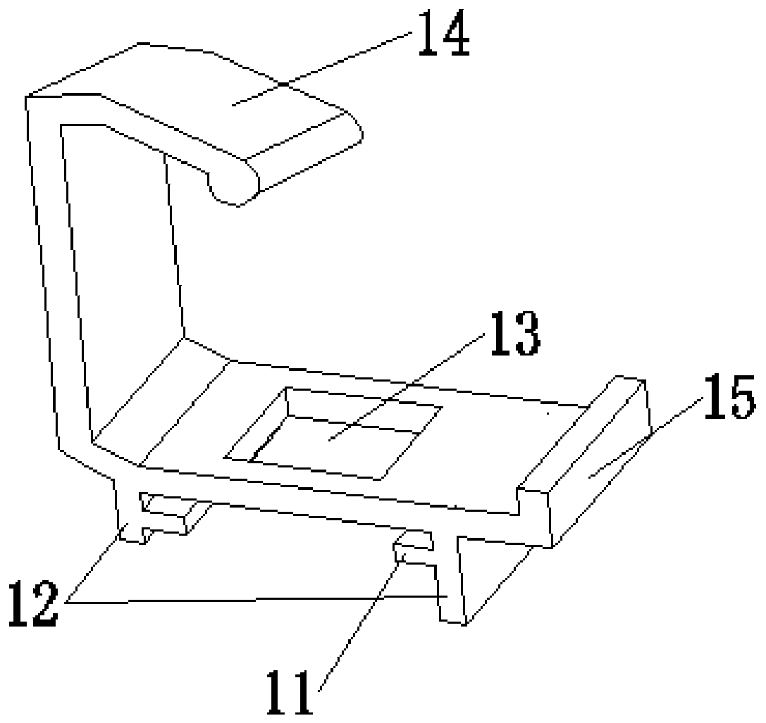
[0025] refer to Figure 1 to Figure 4 As shown, an energy-saving door and window drainage and anti-mosquito structure includes an opening fan 1 and a frame 2, the opening fan 1 is hinged on the frame 2, the bottom side of the frame 2 is provided with a drainage groove 6, and the , and a windproof cover 3 is fixed on the lower end of the drainage groove 6, and a drainage anti-mosquito decorative cover 5 is fastened on the frame 2 and positioned at the upper end of the drainage groove 6, and at least one piece of anti-mosquito decorative cover is placed in the drainage anti-mosquito decorative cover 5 The anti-mosquito net 7 is provided with a drai...


PUM


Abstract

The invention discloses an energy-saving door and window drainage anti-mosquito structure which is simple in structure, good in drainage and wind shielding effect and capable of effectively preventingmosquitoes from entering a room. The structure comprises an opening sash and a frame, the opening sash is hinged to the frame, a drainage groove is formed in a bottom end side of the frame, and a windproof cover is fixed to the position, located at the lower end of the drainage groove, of the frame; a drainage anti-mosquito decorative cover is buckled to the position, located at the upper end ofthe drainage groove, of the frame, at least one or more anti-mosquito nets are placed in the drainage anti-mosquito decorative cover, and a drainage opening is further formed in the position, locatedat the upper end of the anti-mosquito nets, of the drainage anti-mosquito decorative cover.

Description

technical field [0001] The invention relates to the technical fields related to the installation and use of door and window structures, in particular to an energy-saving door and window drainage and anti-mosquito structure and an installation method. Background technique [0002] At present, the existing windows all adopt the frame and pull-out window structure. This structure has the characteristics of convenient installation and wide applicability. It is widely used in urban high-rise buildings, factory buildings and residential areas, and self-built houses in rural areas. The glass window can be opened and closed by using the handle. The existing technology is that most door and window structures will leave two small holes at the bottom of the frame. When it rains heavily in high-rise buildings, this type of door and window will have rainwater leaking into the frame. In general, the function of this hole is to use the hole to effectively discharge the water leaking into t...

Claims


Application Information

Patent Timeline
Patent Type & Authority Applications(China)
IPC IPC(8): E06B7/14E06B9/52A01M29/34
CPCE06B7/14E06B9/52A01M29/34E06B2009/527
Inventor 周志高
Owner 周志高
Learn More