Automatic element cleaning and blowdown system for gas filters
A sewage system and filter technology, applied in the direction of dispersed particle filtration, fuel, gas fuel, etc., to avoid potential safety hazards and achieve the effect of high degree of automation
- Summary
- Abstract
- Description
- Claims
- Application Information
AI Technical Summary
Problems solved by technology
Method used
Image
Examples
Embodiment 1
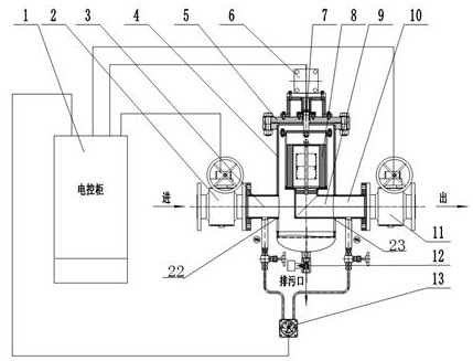
[0027] As a preferred embodiment of the present invention, with reference to the attached figure 2 , this example discloses:
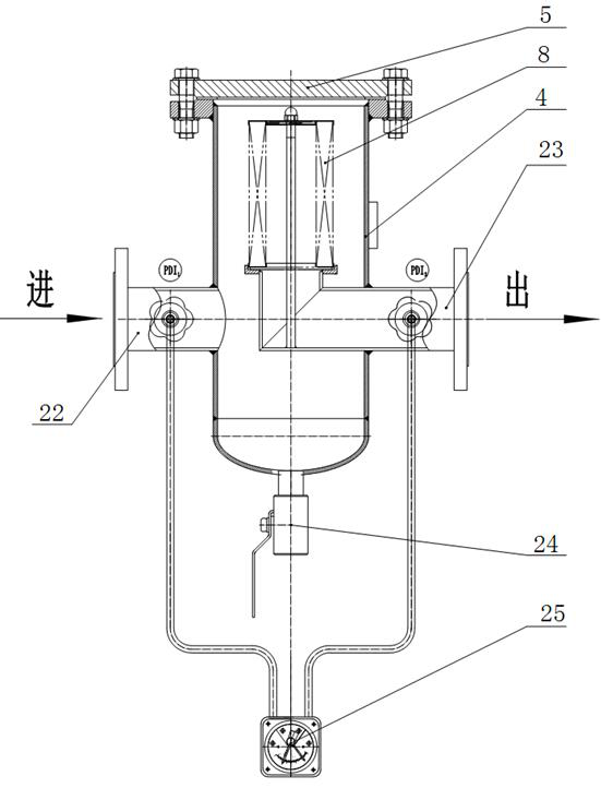
[0028] The automatic filter element cleaning and blowdown system suitable for gas filters includes a gas filter, the gas filter includes a cylinder body 4, a flange cover 5, a filter element 8, a gas inlet 22, a gas outlet 23 and a sewage outlet 24; it also includes Electric control cabinet 1, import electric control valve 2, export electric control valve 11, sewage electric control valve 12, rotary drive 6, rotator 9 and differential pressure transmitter 13; import electric control valve 2, export electric control valve 11, The sewage electric control valve 12, the rotary driver 6 and the differential pressure transmitter 13 are respectively connected to the electric control cabinet 1; the electric control cabinet 1 collects the differential pressure data of the differential pressure transmitter 13, and controls the inlet electric control valve The ...
Embodiment 2
[0033] As another preferred embodiment of the present invention, with reference to the attached Figure 2-3 , this example discloses:
[0034] Such as figure 2 As shown, the automatic filter element cleaning and sewage discharge system suitable for gas filters includes a gas filter, and the gas filter includes a cylinder body 4, a flange cover 5, a filter element 8, a gas inlet 22, a gas outlet 23 and a sewage outlet 24 ; Also includes electric control cabinet 1, import electric control valve 2, export electric control valve 11, sewage electric control valve 12, rotary drive 6, rotator 9 and differential pressure transmitter 13; import electric control valve 2, export electric control valve Valve 11, sewage electric control valve 12, rotary driver 6 and differential pressure transmitter 13 are respectively connected to electric control cabinet 1; electric control cabinet 1 collects pressure difference data of differential pressure transmitter 13 and controls imported electri...
Embodiment 3
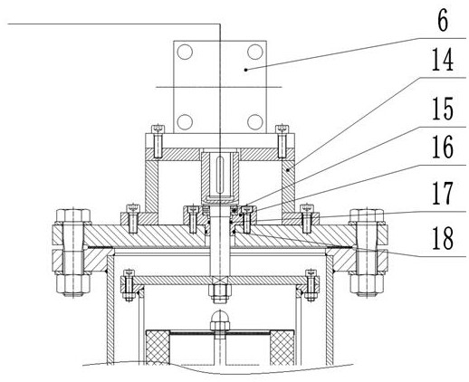
[0037] As another preferred embodiment of the present invention, with reference to the attached Figure 2-4 , this example discloses:
[0038] Such as figure 2 As shown, the automatic filter element cleaning and sewage discharge system suitable for gas filters includes a gas filter, and the gas filter includes a cylinder body 4, a flange cover 5, a filter element 8, a gas inlet 22, a gas outlet 23 and a sewage outlet 24 ; Also includes electric control cabinet 1, import electric control valve, export electric control valve, rotary drive 6, rotator 9 and differential pressure transmitter 13; import electric control valve, export electric control valve, rotary drive 6 and differential pressure transmitter The transmitters 13 are respectively connected with the electric control cabinet 1; the electric control cabinet 1 collects the differential pressure data of the differential pressure transmitter 13, and controls the action of the import electric control valve, the export ele...
PUM
 Abstract
Description
Claims
Application Information
 - R&D
- Intellectual Property
- Life Sciences
- Materials
- Tech Scout
- Unparalleled Data Quality
- Higher Quality Content
- 60% Fewer Hallucinations
Browse by: Latest US Patents, China's latest patents, Technical Efficacy Thesaurus, Application Domain, Technology Topic, Popular Technical Reports.
© 2025 PatSnap. All rights reserved.Legal|Privacy policy|Modern Slavery Act Transparency Statement|Sitemap|About US| Contact US: help@patsnap.com


