Machining method for forming microstructure on surface of workpiece and control system

A technology of workpiece surface and processing method, which is applied in the field of processing and control systems for forming microstructures on the workpiece surface, can solve the problems of low quality of the processed surface, difficult localization, low processing efficiency, etc., so as to improve the coupling rate and improve the processing efficiency. Efficiency and process stability, the effect of ease of flexible fabrication

Active Publication Date: 2020-07-03
SUZHOU UNIV
View PDF9 Cites 5 Cited by
  • Summary
  • Abstract
  • Description
  • Claims
  • Application Information

AI Technical Summary

Problems solved by technology

[0008] The purpose of the present invention is to provide a processing method for forming a microstructure on the surface of a workpiece to solve the problems of low processing surface quality, low processing efficiency and difficult localization, thereby improving the processing efficiency and processing stability of micro-electrolytic machining

Method used


Image

  • Machining method for forming microstructure on surface of workpiece and control system
  • Machining method for forming microstructure on surface of workpiece and control system
  • Machining method for forming microstructure on surface of workpiece and control system

Examples


Embodiment 1

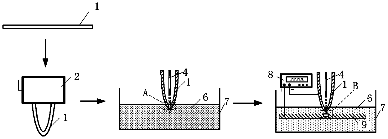
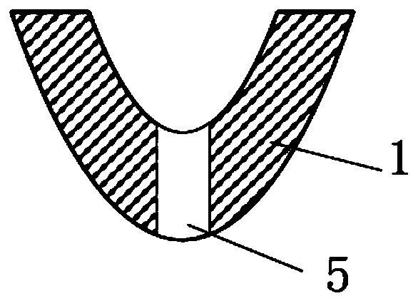
[0043] Step 1, see Figure 1 to Figure 3 , a molybdenum thin plate 1 with a thickness of 50 μm is installed as a cathode 1 in a non-conductive cathode fixture 2 made of plexiglass material. After installation, the molybdenum thin plate 1 will have a certain curvature and form a small curvature surface at the bottom; Cathode 1 and cathode holder 2 were ultrasonically cleaned in alcohol and deionized water for 5 minutes respectively to remove oil and other impurities on the surface of cathode 1 and cathode holder 2, and then the remaining deionized water on the surface of cathode 1 was dried with natural wind. The purpose of bending and fixing the molybdenum thin plate 1 is to make the area of ​​the cathode entering the electrolyte small enough, so as to effectively improve the coupling rate of the laser energy field and the electrochemical energy field in the subsequent laser-electrolysis composite processing process.

[0044] Step 2, see Image 6 , the cathode fixture 2 is fi...

Embodiment 2

[0047] Step 1, see Figure 4 , a tungsten wire 1 with a diameter of 50 μm is used as a cathode 1 and installed in a non-conductive cathode fixture 2 made of organic glass material with a certain tension force, wherein the tension force is 1.0N; the cathode 1 and the cathode fixture 2 Washing and drying, this operation is the same as Step 1 in Example 1, and will not be repeated here.

[0048] Step 2. This step in this embodiment is basically the same as that in Embodiment 1. The control system used is the same control system as that in Embodiment 1. Please refer to Figure 7 , the difference is: the cathode fixture 2 with tungsten wire 1 is fixed on the first three-dimensional precision motion platform 13 in the control system; the tungsten sheet 3 with a thickness of 50 μm is installed in the workpiece fixture 11, and it is fixed on the The second three-dimensional mobile platform 21, then the second three-dimensional mobile platform 21 adjusts it to such as Figure 7 In th...


PUM

PropertyMeasurementUnit
thicknessaaaaaaaaaa
diameteraaaaaaaaaa
diameteraaaaaaaaaa

Abstract

The invention relates to a machining method for forming a microstructure on the surface of a workpiece. The machining method comprises the steps of S1, providing a metal material immersed into electrolyte as a cathode and forming a penetration microstructure penetrating through the cathode on the cathode; and S2, providing a workpiece as an anode, and conducting laser-electrolysis composite machining on the workpiece according to the penetration microstructure on the cathode to form the required microstructure on the surface of the workpiece. By forming the penetration microstructure penetrating through the cathode on the cathode, the coupling ratio of a laser energy field and an electrochemical energy field in the process of forming the required microstructure on the surface of the workpiece through laser-electrolysis composite machining is effectively increased. Accordingly, the electrochemical solution rate of the material can be effectively promoted through a laser beam with the low energy density, the machining efficiency and machining stability of micro electrolytic machining are improved under the condition of hardly affecting the machining locality and machined surface quality, and flexible preparation of the large-area microstructure can be realized easily.

Description

technical field [0001] The invention relates to a processing method and a control system for forming a microstructure on the surface of a workpiece. Background technique [0002] With the continuous advancement of modern science and technology, precision and miniaturization have become the mainstream development direction of industrial, civil and military products, and microfabrication technology is the supporting technology to realize product precision / miniaturization, so it has received extensive attention. Electrolytic Micromachining (ECMM) is a microfabrication method based on the principle of electrochemical anodic dissolution for subtractive machining of metal materials. Compared with other micromachining methods (machining, laser machining, EDM, etc.), ECMM has its unique advantages, including: no loss of tool cathode (reusable), high quality of machined surface (no stress and metamorphic layer, No flash and burrs, etc.), the processing process has nothing to do with...

Claims


Application Information

Patent Timeline
Patent Type & Authority Applications(China)
IPC IPC(8): B23H5/00B23H9/00B23H11/00B23K26/00
CPCB23H5/00B23H9/008B23H11/00B23K26/0093
Inventor 贺海东刘楠王春举孙宇孙立宁宁学中
Owner SUZHOU UNIV
Why Eureka
Try Eureka