
Cable erecting device for building electromechanical installation

An electromechanical technology for installation, applied in the direction of overhead lines/cable equipment, etc., can solve problems such as poor anti-loosening effect, waste of resources, and cable breakage, and achieve the effects of ensuring normal power supply, improving work efficiency, and preventing cable shedding

Active Publication Date: 2020-07-03
BEIJING TIANHENG CONSTR
View PDF9 Cites 13 Cited by
  • Summary
  • Abstract
  • Description
  • Claims
  • Application Information

AI Technical Summary

Problems solved by technology

[0003] Existing cable erection devices generally bury the utility poles underground. In this process, large-scale mechanical equipment is required, which is not only inefficient, but also wastes resources. The staff climbs to the utility poles for cable erection. High, once an accident occurs, it will cause personal injury to the staff. Because the utility pole is in the construction site, it is often touched by some machinery, which may easily cause the utility pole to tilt or even collapse. After the cable is erected, the construction site will fall. Falling stones and other sundries are easy to fall on the cable, which may easily cause short circuit or even cable breakage in the cable power supply, which seriously affects the normal power supply of the construction site. Generally, screw holes or It is to directly open an empty slot to place or fix the cable, but in the process of use, the screw fixing is easy to cause certain damage to the appearance of the cable. The cable is placed in the empty slot. When encountering bad weather, the wire The large swing range of the cable is likely to cause the problem of falling off, and the anti-falling effect is not good

Method used


Image

  • Cable erecting device for building electromechanical installation
  • Cable erecting device for building electromechanical installation
  • Cable erecting device for building electromechanical installation

Examples


Embodiment Construction

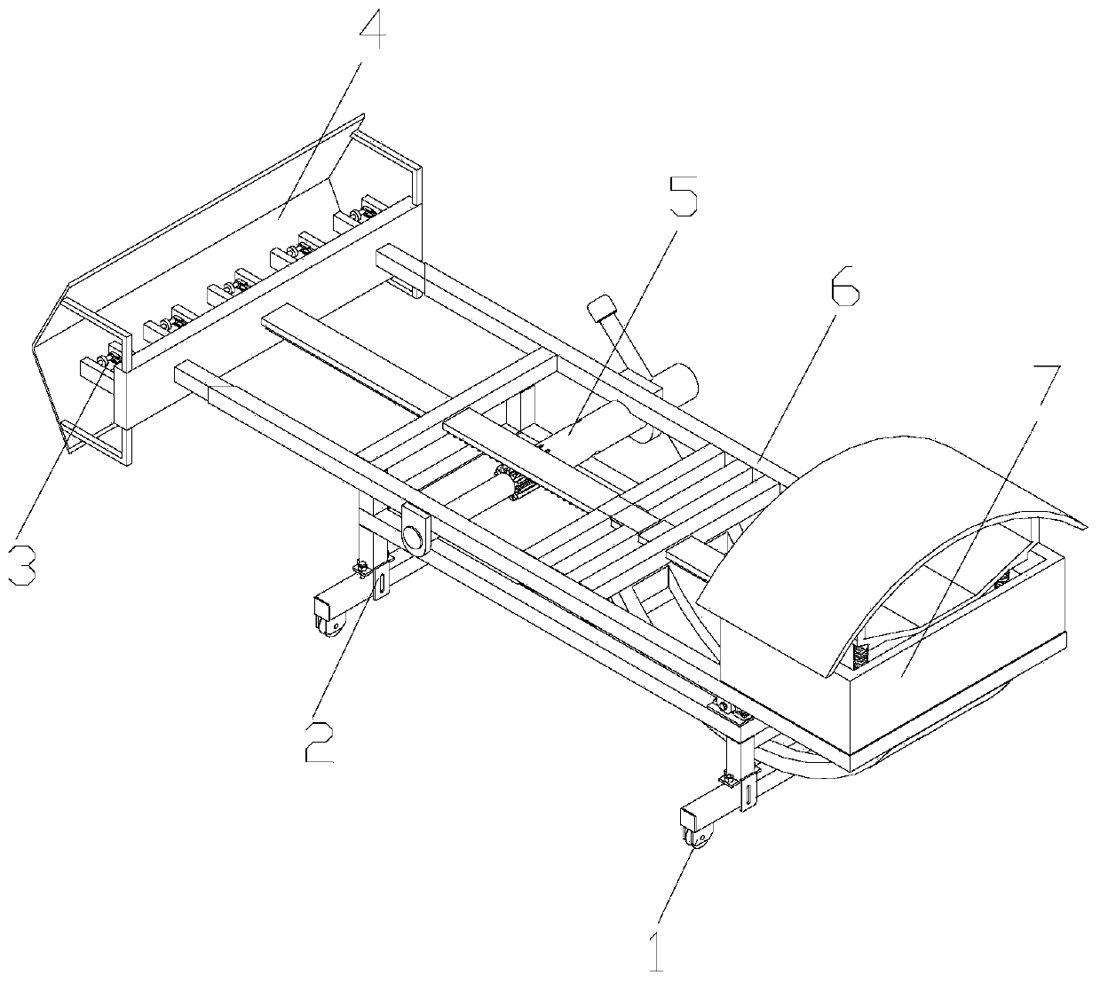
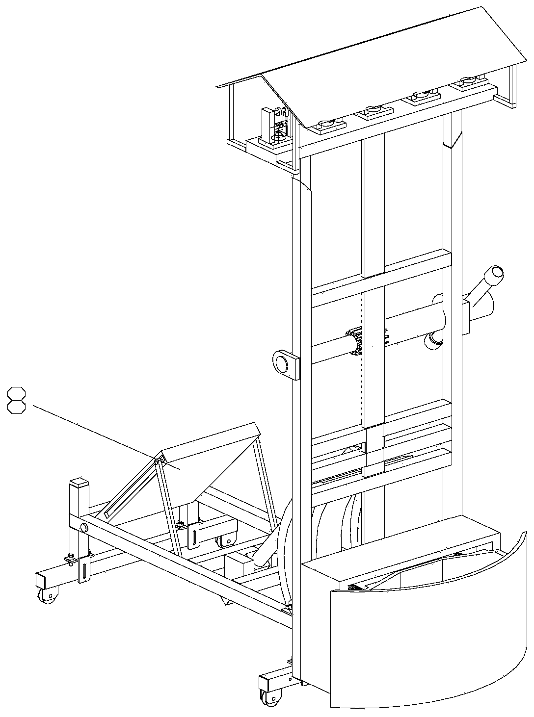
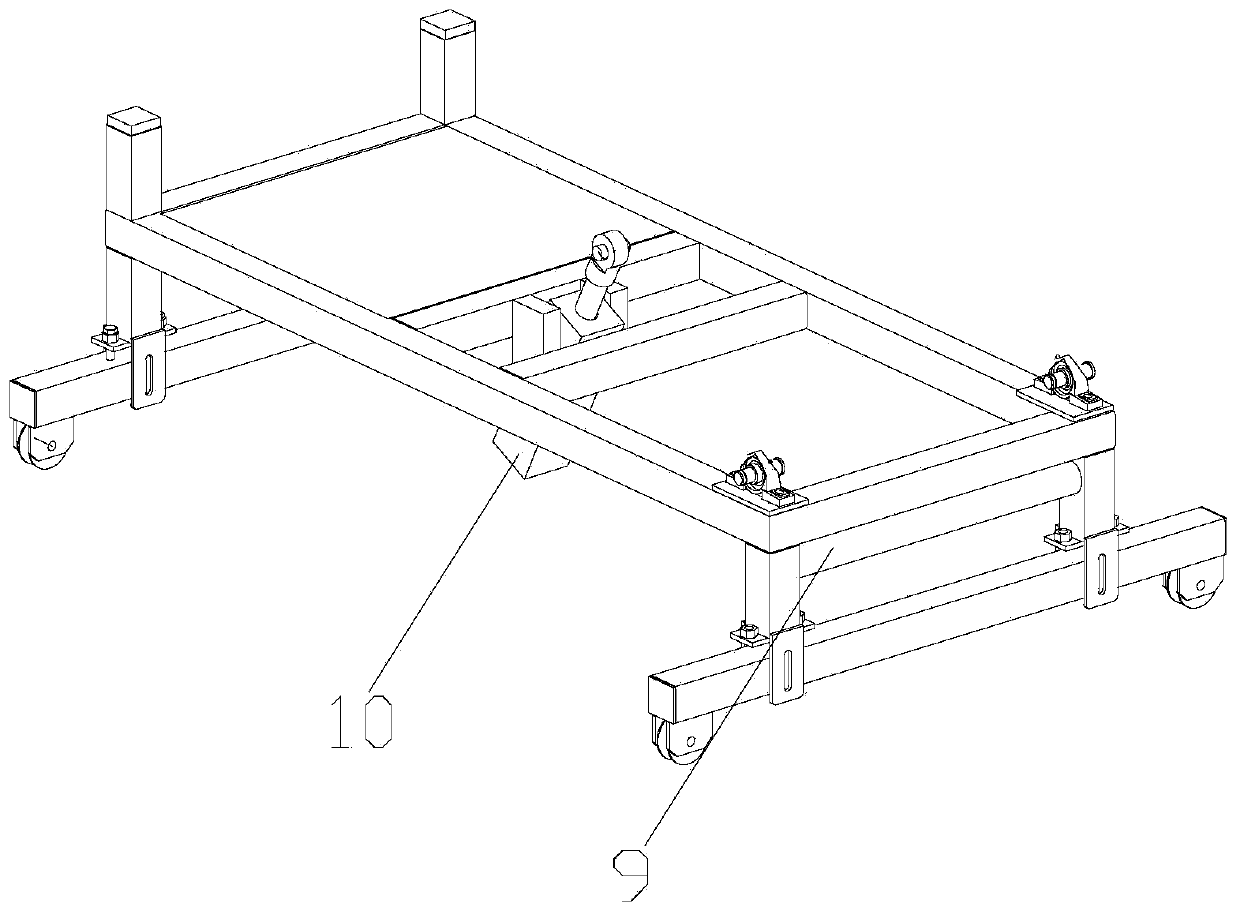
[0034] Attached below Figure 1-10 , clearly and completely describe the technical solutions in the embodiments of the present invention, obviously, the described embodiments are only some of the embodiments of the present invention, not all of them. Based on the embodiments of the present invention, all other embodiments obtained by persons of ordinary skill in the art without making creative efforts belong to the protection scope of the present invention.

[0035] In describing the present invention, it should be understood that the terms "longitudinal", "transverse", "upper", "lower", "front", "rear", "left", "right", "vertical", The orientations or positional relationships indicated by "horizontal", "top", "bottom", "inner", "outer", etc. are based on the orientations or positional relationships shown in the drawings, and are only for the convenience of describing the present invention, rather than indicating or It should not be construed as limiting the invention by impl...


PUM


Abstract

The invention discloses a cable erecting device for building electromechanical installation. The device comprises a fixing frame. A supporting frame and a hydraulic cylinder are installed on the fixing frame. The hydraulic cylinder is installed in the middle of the fixing frame. The supporting rod is matched with the supporting frame. The supporting frame is installed at one end of the fixing frame. A lifting mechanism and a buffering mechanism are installed on the supporting frame. The lifting mechanism is installed in the middle of the supporting frame. The cable fixing mechanism and the protective cover are installed on the lifting mechanism. The cable fixing mechanism is installed at one end of the lifting mechanism, the protective cover is installed at one end of the lifting mechanismand one side of the cable fixing mechanism, and the buffer mechanism is installed at one end of the supporting frame. A worker does not need to climb to a telegraph pole, the purpose of erecting thecable can be achieved only by installing the cable on the cable fixing mechanism and then controlling the hydraulic cylinder to lift the supporting frame, the safety of the worker is guaranteed, and the cable fixing mechanism can prevent the cable from being damaged and can also fix the cable and prevent the cable from falling off.

Description

technical field [0001] The invention belongs to the technical field of cable erection, in particular to a cable erection device for building electromechanical installation. Background technique [0002] In construction projects, some electromechanical equipment needs to be used, but the electromechanical equipment needs to be connected to an external power source for driving. Therefore, some cables need to be erected on the construction site to connect the power to the construction site, and cable erection devices are required in the process of cable pulling. [0003] Existing cable erection devices generally bury the utility poles underground. In this process, large-scale mechanical equipment is required, which is not only inefficient, but also wastes resources. The staff climbs to the utility poles for cable erection. High, once an accident occurs, it will cause personal injury to the staff. Because the utility pole is in the construction site, it is often touched by some ...

Claims


Application Information

Patent Timeline
IPC IPC(8): H02G1/04
CPCH02G1/04
Inventor 贾志彬沈洪杨顺孟胜鹏安乐
Owner BEIJING TIANHENG CONSTR
Learn More