Drag chain structure of movable workbench

A technology of moving worktable and towline, applied in the field of towline, can solve the problems of inability to close, damage of moving worktable, and easy damage of cables, etc., and achieve the effect of reducing the diameter

Pending Publication Date: 2020-07-03
XIANGSHAN YIDUAN PRECISION MACHINERY CO LTD
View PDF0 Cites 0 Cited by
  • Summary
  • Abstract
  • Description
  • Claims
  • Application Information

AI Technical Summary

Problems solved by technology

[0002] With the upgrading of the customer's factory layout, more and more users prefer to adopt the mobile workbench structure, and the control of the mobile workbench needs to lay out the cable structure. At present, there are two conventional methods: tensile cables and drag chains, and tensile cables The installation structure is simple, but the tensile cable is generally a custom-made model, the cost is high, and the cable is easily damaged due to the direct force of the cable, and the service life is long. Lift the cover plates one by one, and close the slot on the bottom surface by closing the cover plate by its own weight. However, because the cover plate is closed by its own weight, the thickness of the cover plate and the structure of the plow share are relatively large, which wastes materials and is cumbersome to install. The plate shaft is rusted and cannot be closed, which will cause certain damage to the mobile workbench, and will also affect the passage of other mechanical equipment in the site.

Method used


Image

  • Drag chain structure of movable workbench
  • Drag chain structure of movable workbench
  • Drag chain structure of movable workbench

Examples


Embodiment Construction

[0024] The following description serves to disclose the present invention to enable those skilled in the art to carry out the present invention. The preferred embodiments described below are only examples, and those skilled in the art can devise other obvious variations.

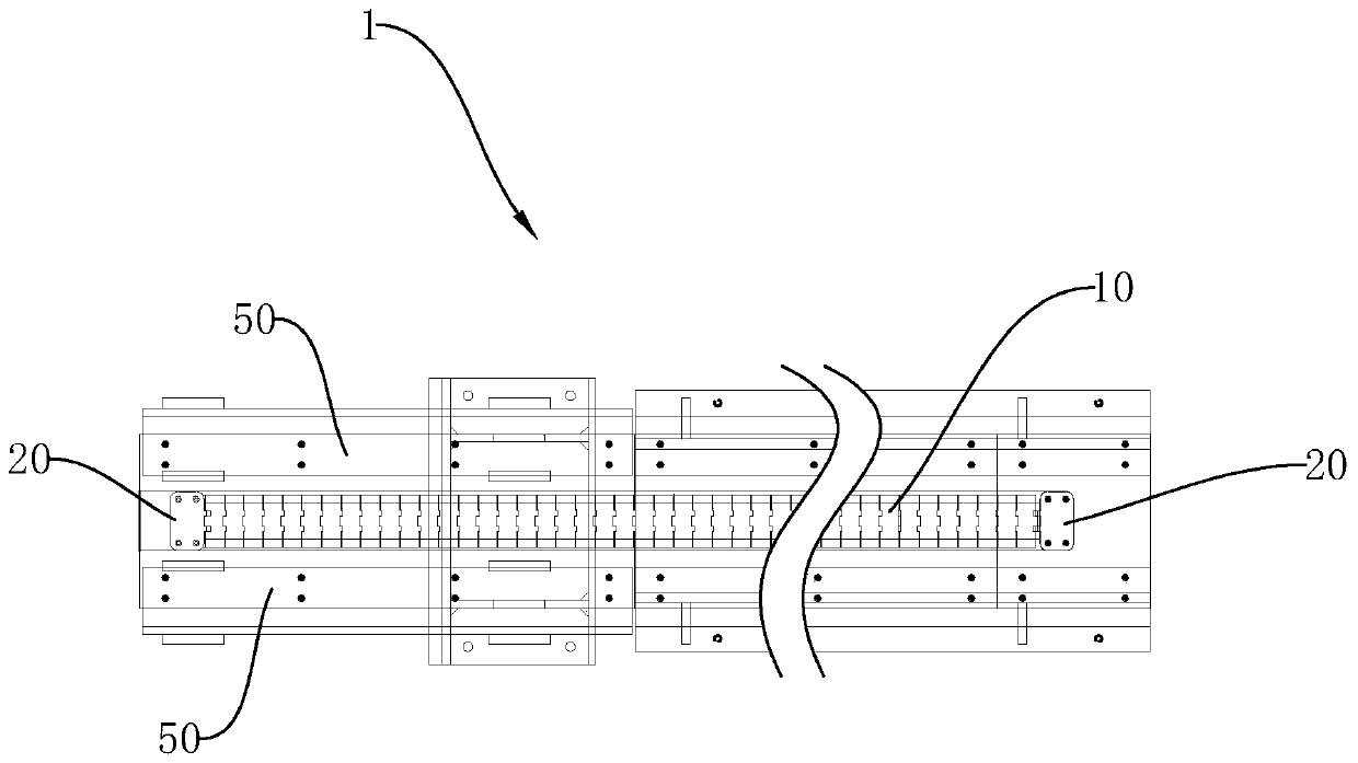
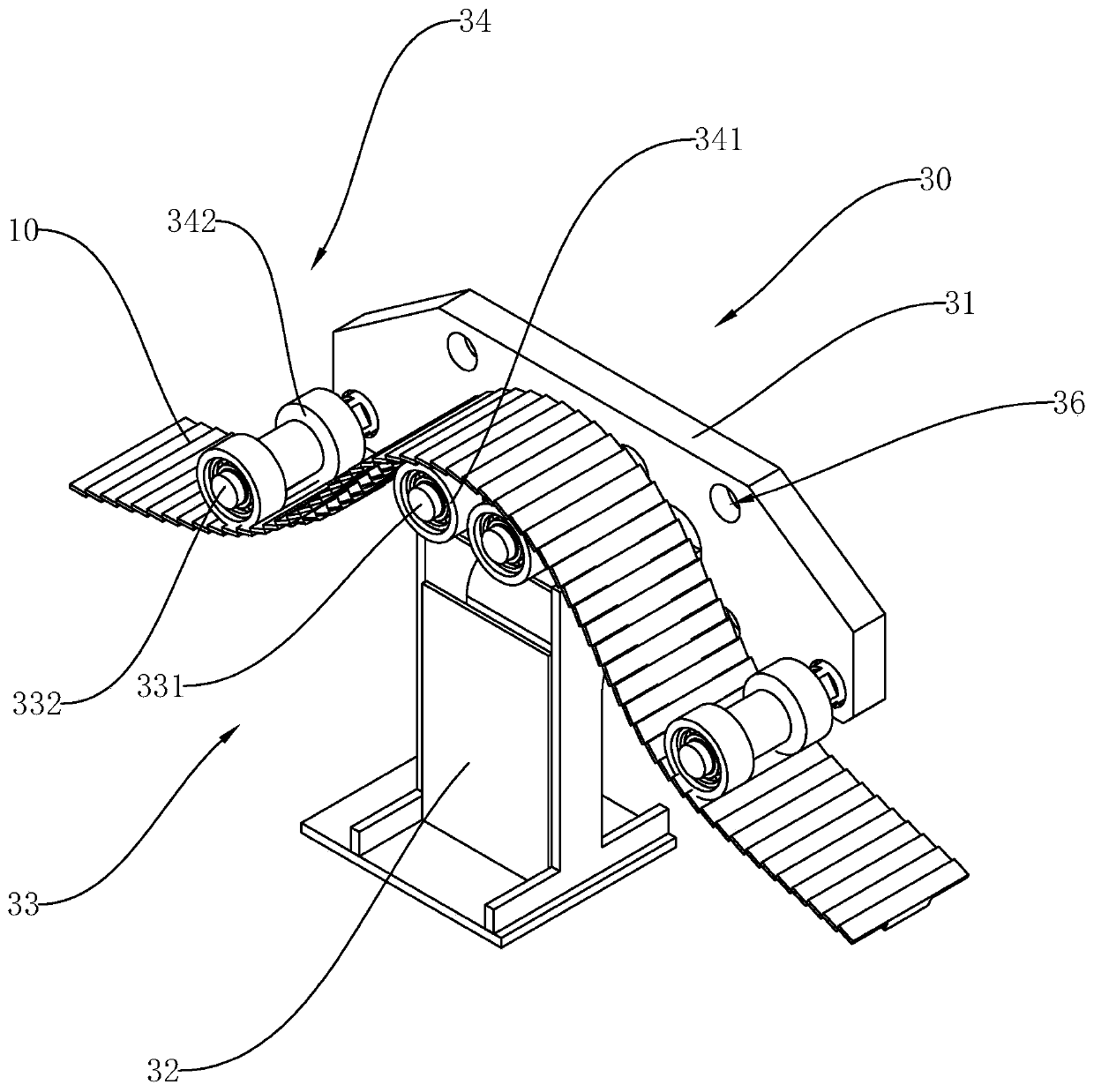
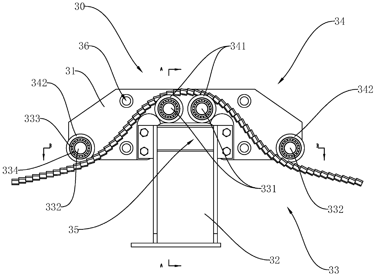
[0025] Such as Figure 1 to Figure 8 Shown is a drag chain structure 1 for a mobile workbench comprising a drag chain body 10, a drag chain fixing plate 20, a jacking device 30, a support seat 40 and a support frame 50, and the drag chain body 10 is laid flat on the support On the frame 50, the support frame 50 is installed on the support base 40, the support base 40 and the support frame 50 are installed in the trench, and the drag chain body 10 is laid flat on the support frame 50 , so that the drag chain body 10 can protect the cables in the trench, and at the same time make the ground surface smooth, which is convenient for pushing other machines to pass without affecting other work; the support frame 5...


PUM


Abstract

The invention provides a drag chain structure of a movable workbench. The drag chain structure comprises a drag chain body, a drag chain fixing plate, a jacking device, a supporting base and a supporting frame. The drag chain body is flatly laid on the supporting frame. The supporting frame is installed on the supporting base. The supporting frame is provided with a containing cavity. The jackingdevice comprises an upper jacking plate and a lower jacking plate. The lower jacking plate is in threaded connection with the upper jacking plate. The lower jacking plate extends into the containing cavity. One end of the drag chain body is fixed to one side of the supporting frame through the drag chain fixing plate, and the other end passes through the jacking device and is fixed on the other side of the supporting frame through the drag chain fixing plate. The drag chain flattening device is simple in overall structure and ingenious and reasonable in design, flattening operation can be effectively conducted on the drag chain body, and passing of other machines and equipment in a site is not affected while power supply operation is achieved.

Description

technical field [0001] The invention relates to the technical field of drag chains, in particular to a drag chain structure of a mobile workbench. Background technique [0002] With the upgrading of the customer's factory layout, more and more users prefer to adopt the mobile workbench structure, and the control of the mobile workbench needs to lay out the cable structure. At present, there are two conventional methods: tensile cables and drag chains, and tensile cables The installation structure is simple, but the tensile cable is generally a customized model, the cost is high, and the cable is easily damaged due to the direct force of the cable, and the service life is long. Lift the cover plates one by one, and close the slot on the bottom surface by closing the cover plate by its own weight. However, because the cover plate is closed by its own weight, the thickness of the cover plate and the structure of the plow share are relatively large, which wastes materials and is...

Claims


Application Information

Patent Timeline
Patent Type & Authority Applications(China)
IPC IPC(8): H02G11/00F16G13/16
CPCF16G13/16H02G11/00
Inventor 谷海军郭洪昌梅碧舟孙明杰杨贤辉王达康梦杰
Owner XIANGSHAN YIDUAN PRECISION MACHINERY CO LTD
Why Eureka
Try Eureka