
Exhibition model rotary exhibition rack

A technology of exhibition racks and models, applied in the field of exhibition racks, can solve the problems of increasing the accommodation pressure of the exhibition venue, inconvenient for exhibitors to watch, and multi-visual blind spots.

Inactive Publication Date: 2020-07-07
SHANGHAI UNIV OF ENG SCI
View PDF5 Cites 1 Cited by
  • Summary
  • Abstract
  • Description
  • Claims
  • Application Information

AI Technical Summary

Problems solved by technology

[0003] In an exhibition, the space is limited and there are many exhibitors. Usually, multiple products need to be placed on one exhibition shelf. If there is only one platform for placing exhibits on the turntable, then in order to avoid the middle exhibits being blocked, the placement of exhibits can only be reduced. , leading to the need to place a large number of exhibition racks in the exhibition to match the number of exhibited products, increasing the pressure of the exhibition venue; and if the turntable is equipped with a multi-layered platform for placing exhibits, when placing, the exhibits need to be stacked layer by layer. There are many people in the exhibition. Exhibitors Generally, they are unwilling to bend down to look at the exhibits, which makes it easy for exhibits located at low places to be overlooked, and exhibits located at high places, especially those above people's heads, are not convenient for exhibitors to watch. Generally speaking, there are more visual blind spots, which makes the display effect of exhibits poor; in addition, such exhibition racks also lack interest during exhibitions, and it is difficult to highlight the characteristics of exhibits, and it is not easy to arouse the interest of exhibitors.

Method used


Image

  • Exhibition model rotary exhibition rack
  • Exhibition model rotary exhibition rack
  • Exhibition model rotary exhibition rack

Examples


Embodiment 1

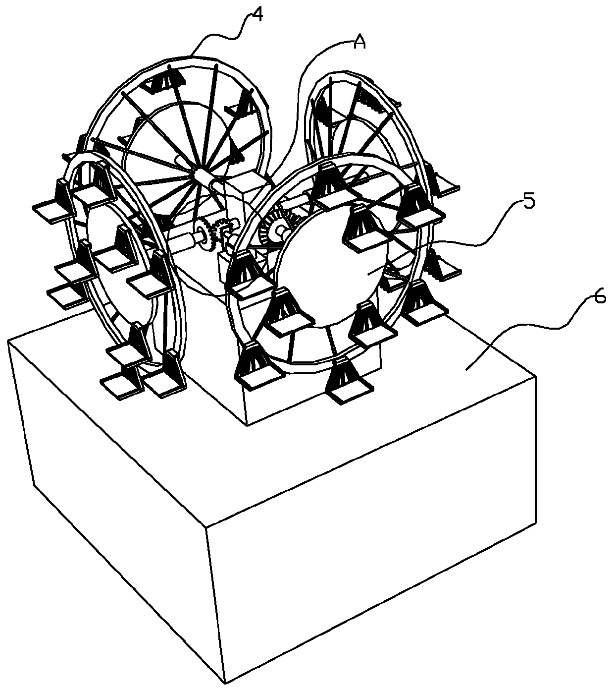
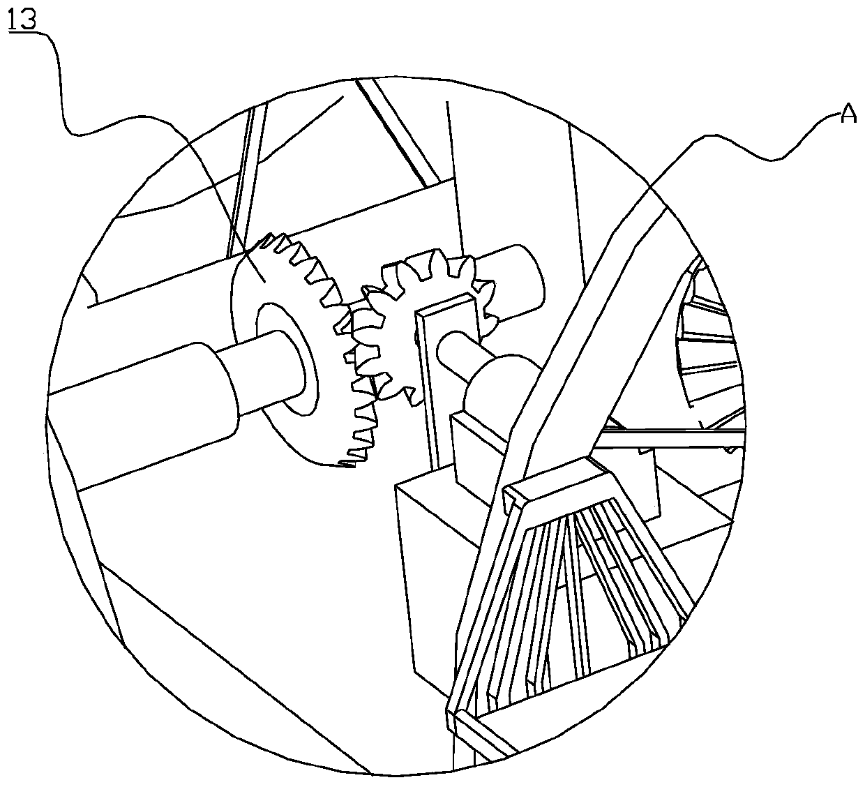
[0051] Please refer to figure 1 , figure 2 As shown, this embodiment provides an exhibition model rotating display stand for displaying exhibitors in the exhibition. It is the same as the conventional display stand, and is provided with a supporting base 6. The difference is that it also includes :

[0052] The first bearing shaft 1, the first bearing shaft 1 is cylindrical and made of a material with strong load-bearing capacity, such as steel, aluminum or other alloys, and the first bearing shaft 1 is sleeved with a first annular sleeve 7 , the first annular sleeve 7 is evenly distributed with a plurality of first connecting rods 8 along the circumferential direction, and a plurality of limiting grooves parallel to the length direction of the first annular sleeve 7 are uniformly arranged on the first annular sleeve 7, the said The first load-bearing shaft 1 and the second load-bearing shaft 2 are provided with limit protrusions that match the limit grooves. When assemblin...

Embodiment 2

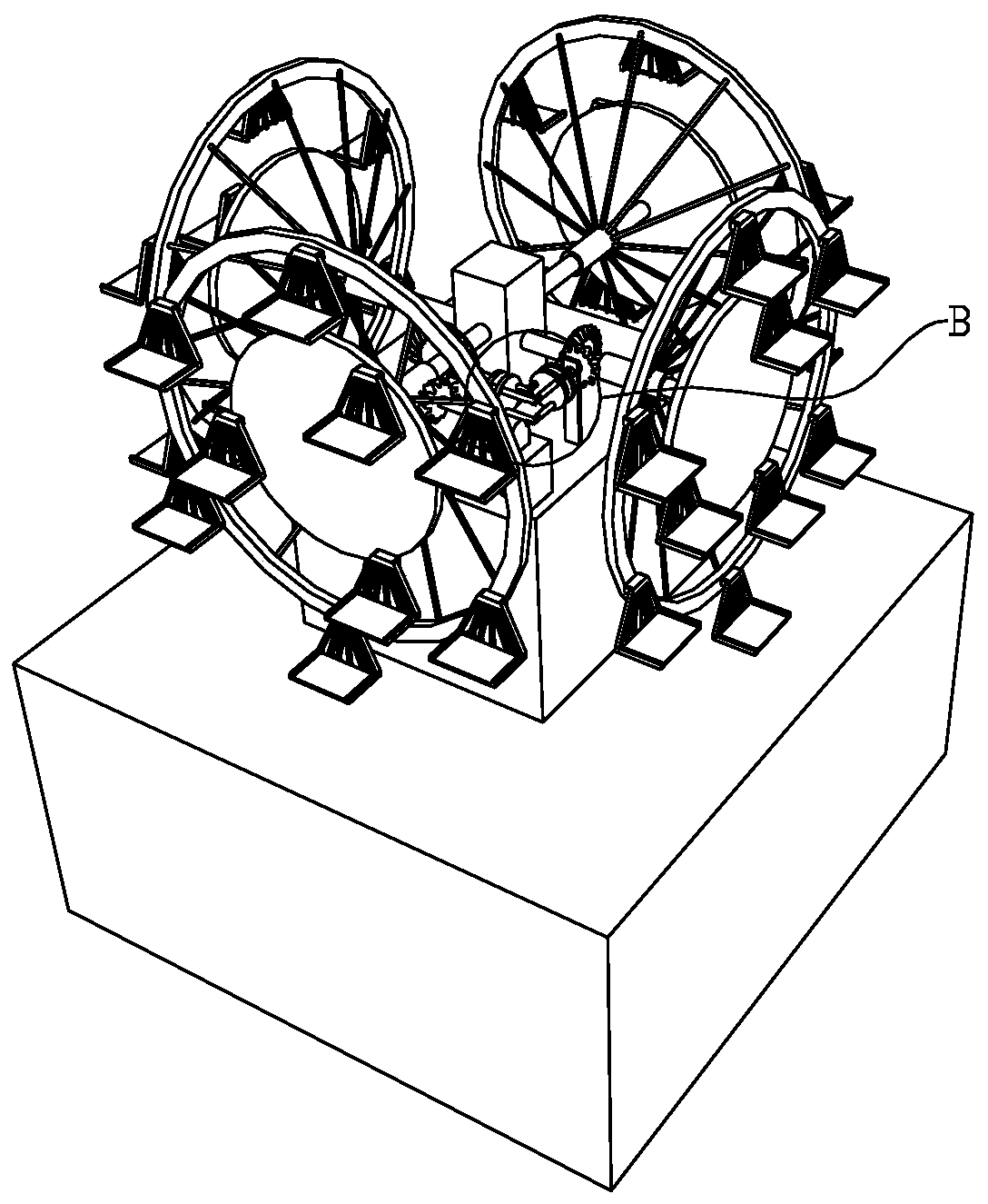
[0061] Please refer to Figure 3-7 As shown, this embodiment is substantially the same as Embodiment 1, the difference mainly lies in the different driving devices, the connection between the first annular sleeve 7 and the first bearing shaft 1, the second annular sleeve and the second bearing shaft 2 The relationship is different, as follows:

[0062] The drive unit includes:

[0063] The first gear 14 is fixedly sleeved on the first bearing shaft 1 or the second bearing shaft 2, and is located between the first annular sleeve 7 and the support column 3, or the second annular sleeve Between the cylinder and the support, and the first gear 14 meshes with the second gear 15, and the second gear 15 drives the first gear 14 to rotate.

[0064] A universal transmission, including a first transmission assembly and a second transmission assembly, the first transmission assembly and the second transmission assembly include two coaxially arranged linkage discs 11, and a linkage shaf...


PUM


Abstract

The invention discloses an exhibition model rotating exhibition frame, and the frame comprises a first bearing shaft, wherein first annular sleeves are arranged at the two ends of the first bearing shaft in a sleeving mode, and a plurality of first connecting rods are evenly distributed on the first annular sleeves in the circumferential direction; a second bearing shaft, wherein second annular sleeves are arranged at the two ends of the second bearing shaft in a sleeving mode, and a plurality of second connecting rods are evenly distributed on the second annular sleeves in the circumferential direction; an annular rotary disc, wherein a plurality of hangers for hanging exhibits are uniformly distributed on the annular rotary disc; a circular rotary disc which is fixedly connected with the end part of the first bearing shaft or the second bearing shaft, wherein a plurality of hangers are uniformly distributed on the edge of the circular rotary disc; a driving device, a supporting column and a base. According to the invention, the containing capacity of the exhibition rack can be increased, exhibits can be displayed in all directions, and the exhibition effect of the exhibits is improved.

Description

technical field [0001] The invention relates to the technical field of exhibition racks, in particular to a rotating exhibition rack for exhibition models. Background technique [0002] Exhibition racks are equipment used to display exhibits to users. They are widely used in exhibitions. In order to facilitate exhibitors to understand their products at exhibitions, product models are generally made and placed on exhibition racks for display. Existing exhibition racks are generally turntable-type, with a turntable for placing exhibits in the middle, and transparent baffles around the turntable, through which exhibitors can watch the exhibits on the turntable. [0003] In an exhibition, the space is limited and there are many exhibitors. Usually, multiple products need to be placed on one exhibition shelf. If there is only one platform for placing exhibits on the turntable, then in order to avoid the middle exhibits being blocked, the placement of exhibits can only be reduced....

Claims


Application Information

Patent Timeline
Patent Type & Authority Applications(China)
IPC IPC(8): A47F5/03
CPCA47F5/03
Inventor 杜欣阳王春娇刘新月许传宏
Owner SHANGHAI UNIV OF ENG SCI
Learn More