Fuel system and rail vehicle
A fuel system and rail vehicle technology, applied in the field of rail vehicle power supply, can solve problems such as fuel leakage
- Summary
- Abstract
- Description
- Claims
- Application Information
AI Technical Summary
Problems solved by technology
Method used
Image

Examples
Embodiment 1
[0041] This embodiment provides a fuel system that can be applied to rail vehicles, specifically to diesel locomotives. The fuel system can be used not only in high-low board diesel locomotives, but also in low-floor diesel locomotives, especially for low-floor diesel locomotives. Issues with collisions with ground obstacles.
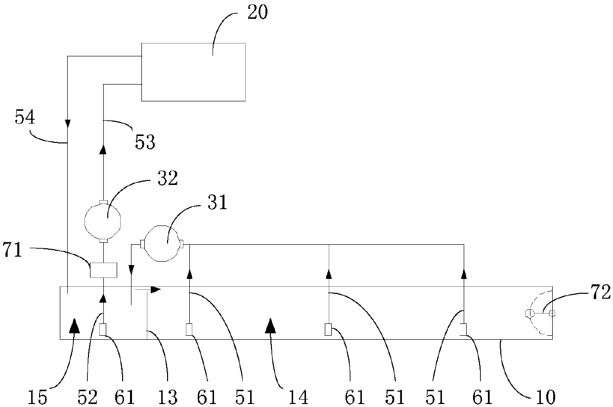
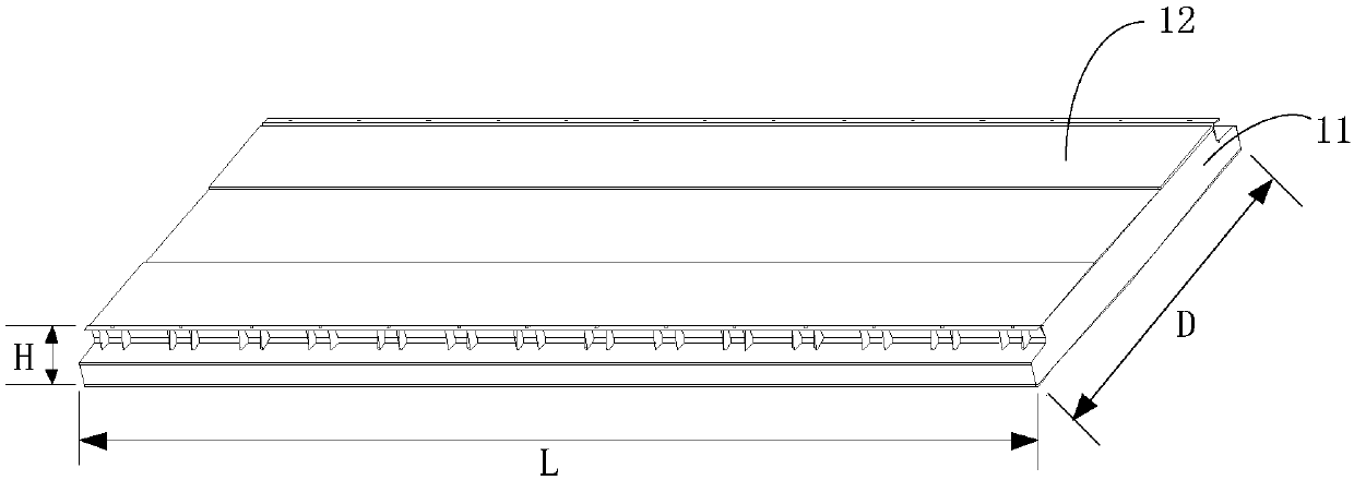
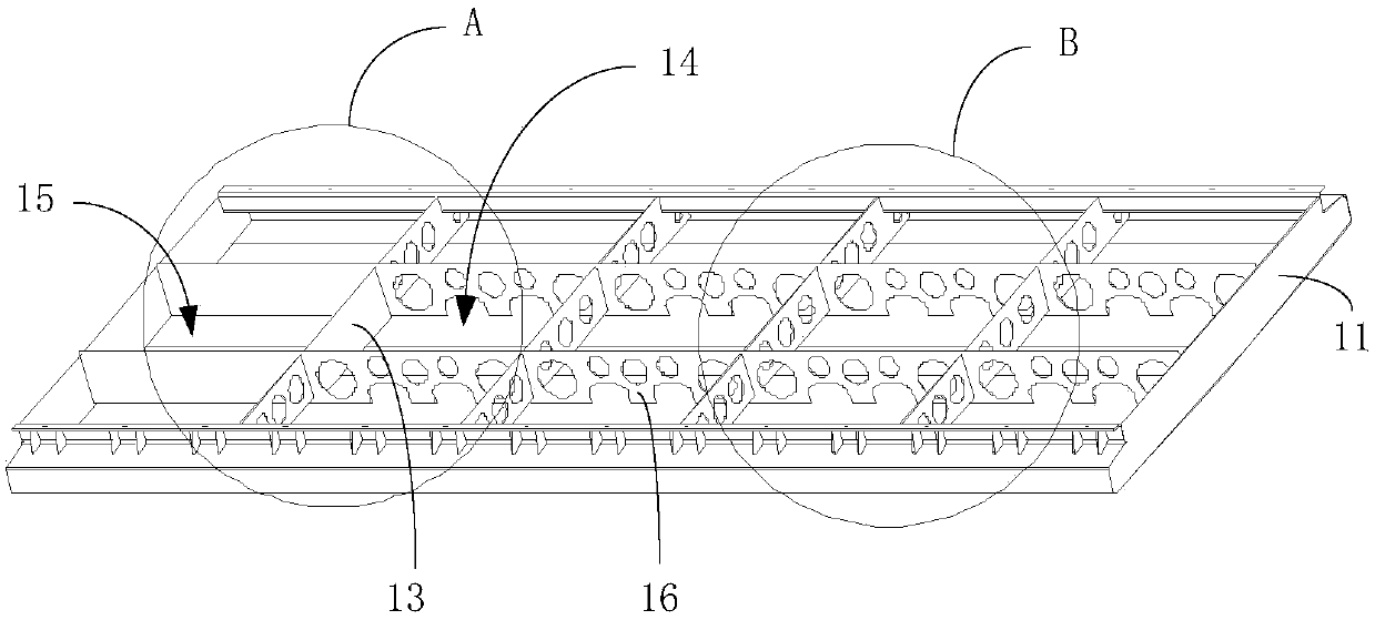
[0042] figure 1 It is a schematic structural diagram of the fuel system provided in Embodiment 1 of the present application, figure 2 It is a schematic structural diagram of the fuel tank provided in Embodiment 1 of the present application, image 3 It is a schematic structural diagram of the tank in the fuel tank provided in Embodiment 1 of the present application. Such as Figure 1 to Figure 3 As shown, the fuel system provided by this embodiment includes: a first fuel tank 10, an internal combustion engine 20 and a first fuel pump 31, and the first fuel tank 10 is arranged at the bottom of the rail vehicle.
[0043] The first fuel tank 10 inclu...
Embodiment 2
[0068] This embodiment provides another fuel system on the basis of the above embodiments.
[0069] Figure 6 It is a schematic structural diagram of the fuel system provided in Embodiment 2 of the present application. Such as Figure 6 As shown, the fuel system provided in this embodiment includes: a first fuel tank 10 , a second fuel tank 40 , a first fuel pump 31 , a second fuel pump 32 , a third fuel pump 33 and an internal combustion engine 20 . Wherein, the first fuel tank 10 adopts the realization method provided by any solution of the above-mentioned embodiments, and the first fuel tank 10 is arranged at the bottom of the rail vehicle. The second oil tank 40 can adopt the oil tank commonly used in the prior art, and is arranged on the top of the rail vehicle.
[0070] The first oil pump 31 is used to pump the fuel in the first chamber 14 of the first fuel tank 10 into the second chamber 15 . The second fuel pump 32 is used to pump the fuel in the second chamber 15 ...
Embodiment 3
[0075] This embodiment provides a rail vehicle, including: the fuel system provided by any one of the above embodiments.
[0076] In the technical solution provided by this embodiment, the first fuel tank can be arranged at the bottom of the rail vehicle, the first fuel tank includes a cavity for containing fuel and a first partition vertically arranged in the cavity, the first partition The plate divides the containing cavity into a first chamber with a larger volume and a second chamber with a smaller volume, and the first oil pump is used to pump the fuel in the first chamber to the second chamber, so that the fuel in the second chamber The height of the fuel oil level is relatively high, and it is not easy to cause air suction; and the first fuel tank provided by this embodiment can be set according to the height of the rail vehicle floor, if it is set to a flat shape, it can adapt to vehicles with low floors, and avoid excessive fuel tank position. The problem arises of b...
PUM
| Property | Measurement | Unit |
|---|---|---|
| Height | aaaaa | aaaaa |
Abstract
Description
Claims
Application Information
 - R&D
- Intellectual Property
- Life Sciences
- Materials
- Tech Scout
- Unparalleled Data Quality
- Higher Quality Content
- 60% Fewer Hallucinations
Browse by: Latest US Patents, China's latest patents, Technical Efficacy Thesaurus, Application Domain, Technology Topic, Popular Technical Reports.
© 2025 PatSnap. All rights reserved.Legal|Privacy policy|Modern Slavery Act Transparency Statement|Sitemap|About US| Contact US: help@patsnap.com