Water tightness test device for electronic equipment case

A test device and electronic equipment technology, applied in the direction of liquid tightness measurement using liquid/vacuum degree, etc., can solve the problems of cumbersome, labor, and unstable placement of the chassis

Pending Publication Date: 2020-07-07
NO 54 INST OF CHINA ELECTRONICS SCI & TECH GRP
View PDF0 Cites 2 Cited by
  • Summary
  • Abstract
  • Description
  • Claims
  • Application Information

AI Technical Summary

Problems solved by technology

[0003] At present, the methods of chassis water test are mainly divided into three methods: dripping, flushing and immersion. According to the different protection requirements of the equipment, related tests are carried out, and the methods used are also different. The dripping test is mainly carried out in the open rain. It is greatly affected by the weather. The flushing test is mainly carried out by using a shower, which needs to be manually held to meet different angles. The method needs to be carried out manually. To a certain depth of water, soak for a corresponding time, but when the chassis is immersed in the water tank, it is usually to add a certain amount of heavy objects to the chassis to make the chassis sink to a certain depth, but the internal weight of the chassis is often unevenly distributed, and the chassis sinks After that, there may be a certain degree of overturning, and the chassis may not be placed stably.
[0004] Based on the above analysis, it can be found that there are some deficiencies in the existing watertightness testing methods: the current watertightness testing methods do not have a unified device that can satisfy the above-mentioned related tests at the same time, and the test methods are greatly affected by artificial and weather factors. , the test is relatively cumbersome, and the labor cost of the test itself will be high

Method used


Image

  • Water tightness test device for electronic equipment case
  • Water tightness test device for electronic equipment case
  • Water tightness test device for electronic equipment case

Examples


Embodiment Construction

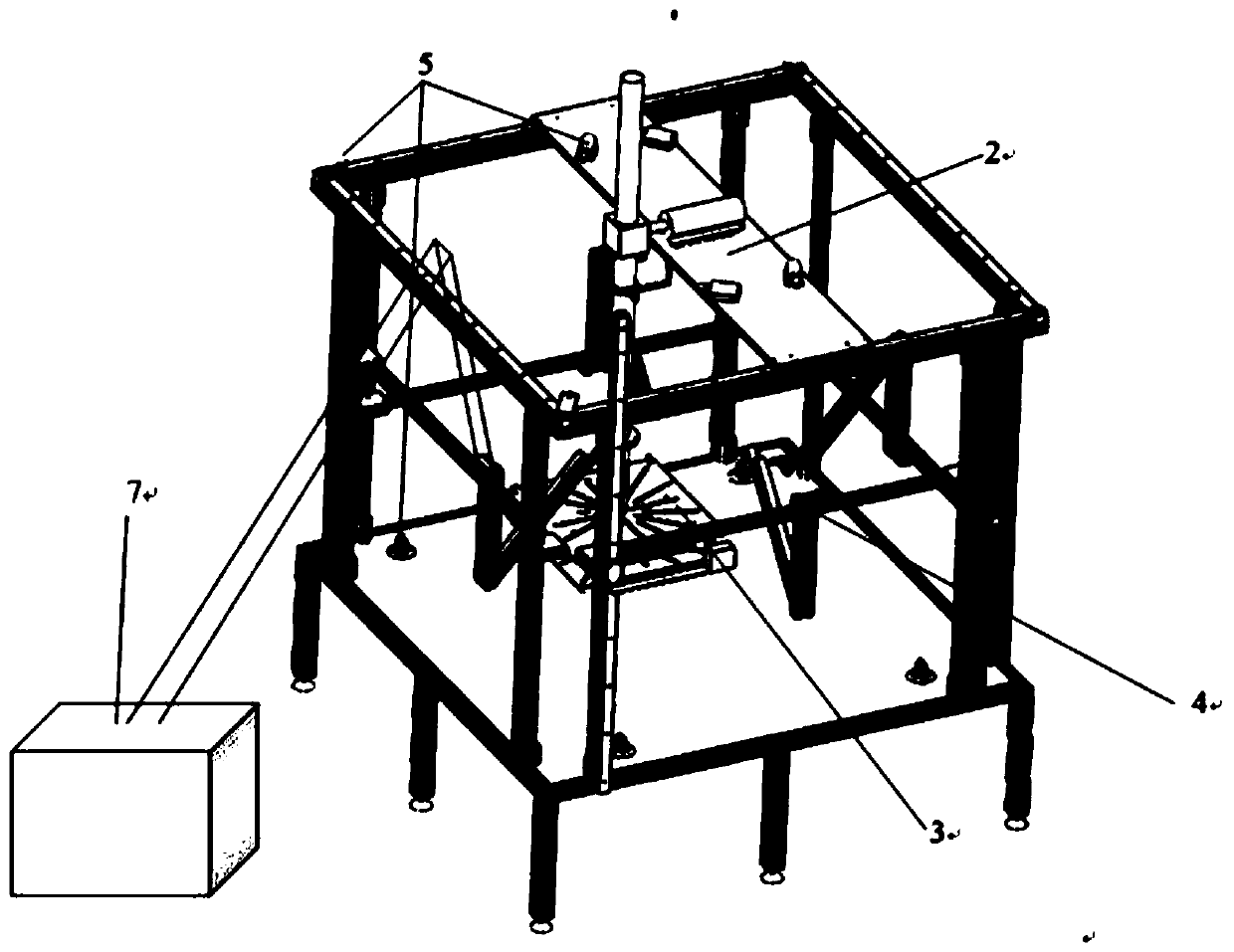
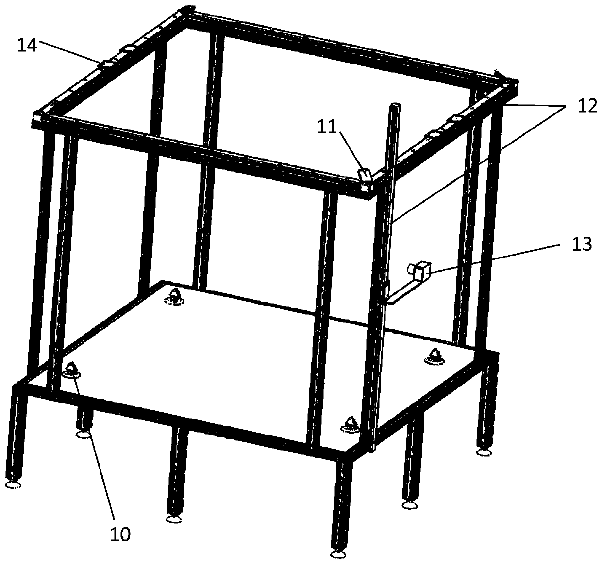
[0027] According to the attached Figure 1-5 The present invention is described further:

[0028] The overall test conditions of the watertightness test device for electronic equipment chassis are divided into dripping, flushing and submerged working states. The specific implementation plan is as follows:

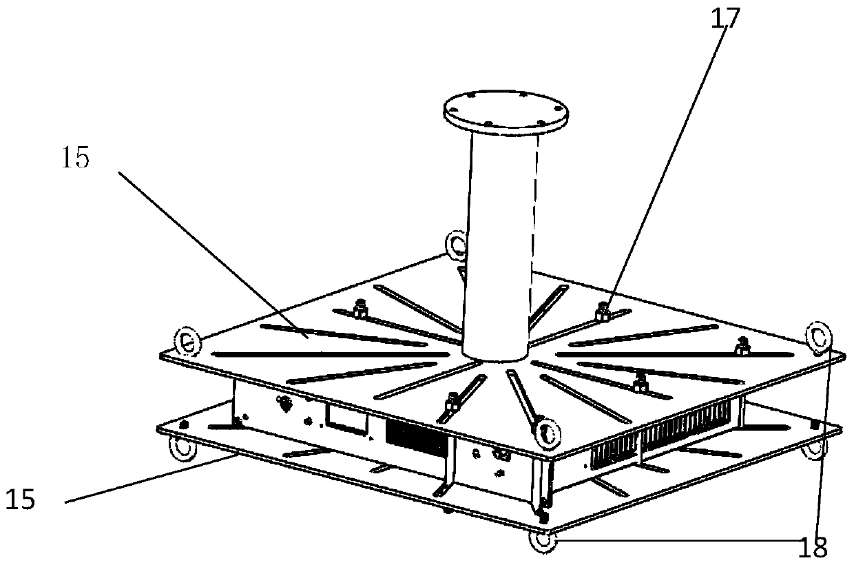
[0029] A watertight test device for an electronic equipment case, comprising a water tank and a lifting structure, the lifting structure includes a lifting rod extending into the water tank, a driving motor arranged on the water tank for driving the movement of the lifting rod, and a lifting rod arranged at the bottom of the lifting rod A platform for placing the chassis to be tested at the end;

[0030] The platform is also connected with multiple groups of suspension assemblies for maintaining the levelness of the platform, and each group of suspension assemblies includes a horizontal motor located above the platform, a first pulley located on the bottom surface of the w...


PUM


Abstract

The invention discloses a water tightness test device for an electronic equipment case, and belongs to the technical field of water tightness test of electronic equipment. The device comprises a watertank and a lifting structure. The lifting structure comprises a lifting rod extending into the water tank, a driving motor arranged on the water tank and used for driving the lifting rod to move, anda platform arranged at the bottom end of the lifting rod and used for placing a to-be-tested case. The platform is further connected with a plurality of sets of hanging assemblies used for keeping the levelness of the platform. Each set of hanging assembly comprises a horizontal motor arranged above the platform, a first pulley arranged on the bottom face of the water tank and a second pulley arranged on the upper edge of the water tank. An output head of each horizontal motor is wound with a balance line, and the balance lines sequentially pass through the first pulleys and the second pulleys and are finally connected to hooks arranged on the upper surface of the clamping platform. The electronic equipment watertight case test technology is mainly improved, the water tightness test device can adapt to cases of different forms, the test depth of a case can be accurately adjusted, and control over test variables is clearer.

Description

technical field [0001] The invention belongs to the technical field of water-tightness testing of electronic equipment, in particular to a water-tightness testing device for electronic equipment casings. Background technique [0002] With the rapid development of the current communication industry, electronic equipment chassis are widely used in military and civilian applications. Since most of the components in the equipment are electronic components, the working environment is often harsh, which requires the chassis to have certain waterproof performance. , in the design process of the chassis, its watertight performance is its main index. [0003] At present, the methods of chassis water test are mainly divided into three methods: dripping, flushing and immersion. According to the different protection requirements of the equipment, related tests are carried out, and the methods used are also different. The dripping test is mainly carried out in the open rain. It is great...

Claims


Application Information

Patent Timeline
IPC IPC(8): G01M3/02
CPCG01M3/02
Inventor 张婉萍孙守超程晓静吴丹肖小龙
Owner NO 54 INST OF CHINA ELECTRONICS SCI & TECH GRP
Why Eureka
Try Eureka