Fuel cell vehicle

A technology for fuel cell vehicles and battery cells, which is applied in fuel cells, power system fuel cells, electric vehicles, etc., and can solve problems such as stack damage, cost increase, and damage

Pending Publication Date: 2020-07-07
TOYOTA JIDOSHA KK
View PDF5 Cites 0 Cited by
  • Summary
  • Abstract
  • Description
  • Claims
  • Application Information

AI Technical Summary

Problems solved by technology

In a general fuel cell vehicle, when the fuel cell vehicle collides with a rigid body and the electric stack has no trauma, it is impossible to judge whether the battery cells of the electric stack have moved laterally or not only by visual inspection of the electr

Method used


Image

  • Fuel cell vehicle
  • Fuel cell vehicle
  • Fuel cell vehicle

Examples


Embodiment approach 1

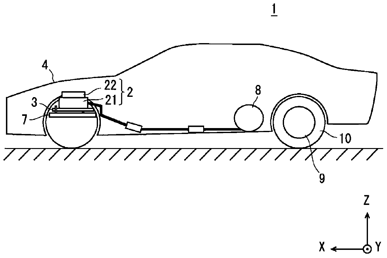
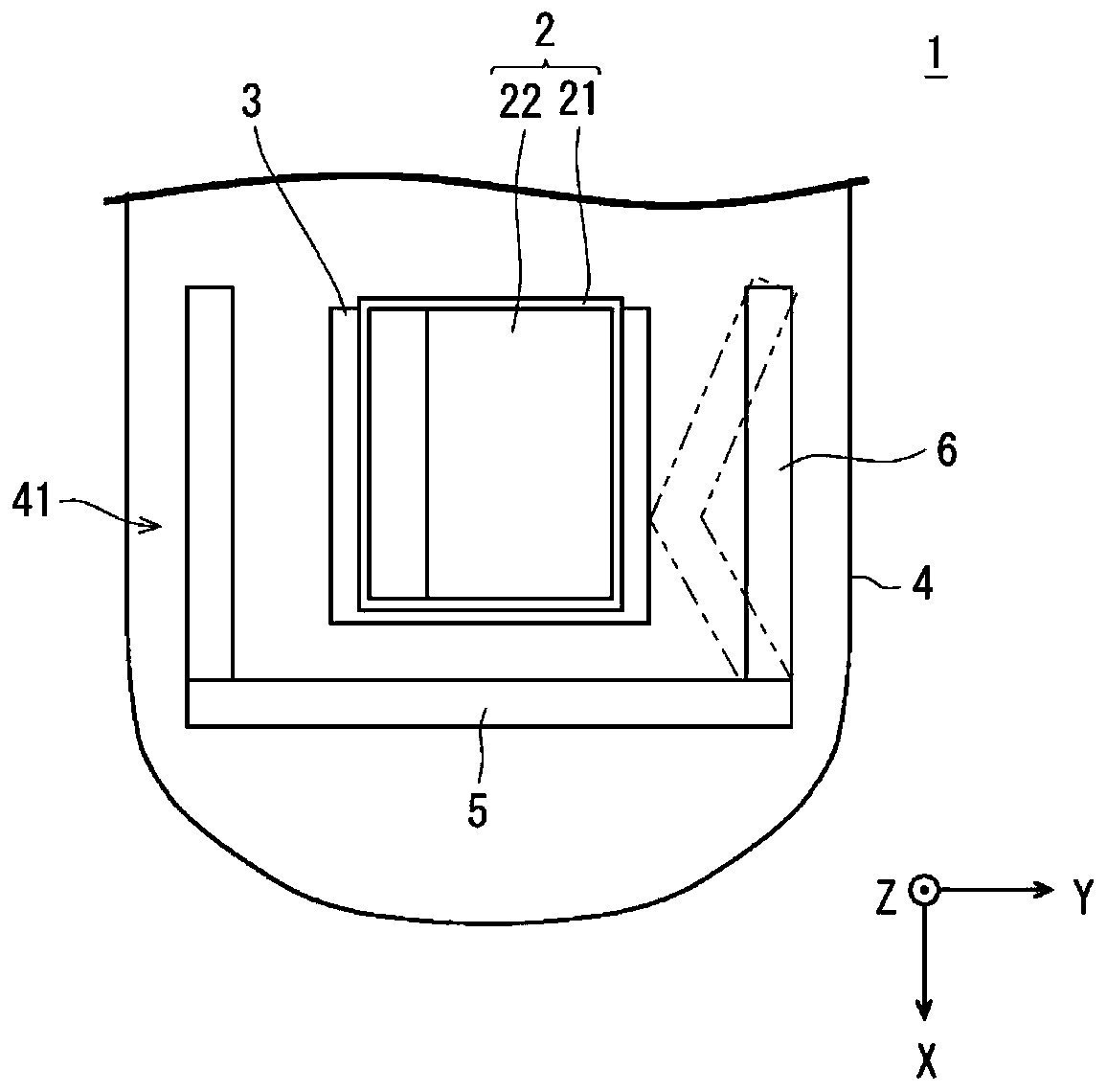
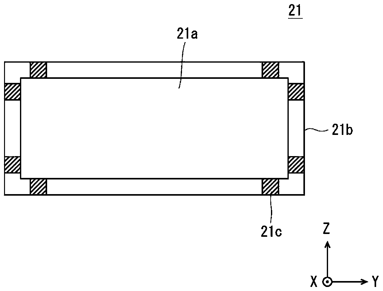
[0030] First, the basic structure of the fuel cell vehicle of this embodiment will be briefly described. figure 1 It is a figure schematically showing the fuel cell vehicle of this embodiment. figure 2 It is a plan view showing the interior of the front compartment of the fuel cell vehicle in this embodiment in a simplified manner. image 3 It is a cross-sectional view showing a simplified stack main body of the fuel cell vehicle according to the present embodiment.

[0031] Here, in the following description, in order to clarify the description, a three-dimensional (XYZ) coordinate system will be used for description. In addition, the positive side of the X-axis is the front side of the fuel cell vehicle, the negative side of the X-axis is the rear side of the fuel cell vehicle, the positive side of the Y-axis is the left side of the fuel cell vehicle, and the negative side of the Y-axis is the fuel cell vehicle The right side of the Z-axis is the upper side of the fuel ce...

Embodiment approach 2

[0064] Figure 10 It is an enlarged view schematically showing the periphery of the fragile portion in the fuel cell vehicle of the present embodiment. In addition, in Figure 10 In , the boundary between the stack frame and the fragile part is shown by a two-dot chain line. In Embodiment 1, the weak portion 17 protrudes from each side 3 a of the stack frame 3 and the part on the positive side of the Z-axis of the side 3 b to the outside of the stack frame 3 , but from each side 3 a of the stack frame 3 And the position in the Z-axis direction where the side surface 3b protrudes is not limited. For example, if Figure 10 As shown, it may protrude toward the outside of the stack frame 3 from the approximate center in the Z-axis direction of the side surface 3 a ( 3 b ) of the stack frame 3 .

Embodiment approach 3

[0066] Figure 11 It is an enlarged view schematically showing the periphery of the fragile portion in the fuel cell vehicle of the present embodiment. In addition, in Figure 11 In , the boundary between the stack frame and the fragile part is shown by a two-dot chain line. The YZ cross-sectional shape of the fragile portion 17 in Embodiment 1 is substantially rectangular, but the YZ cross-sectional shape of the fragile portion 17 is not limited. At this point, for example, you can Figure 11 As shown, the YZ cross section is made into a substantially triangular shape so that the height (thickness) of the fragile portion 17 in the Z-axis direction becomes thinner toward the outer side of the stack frame 3 .

[0067] Here, the XZ cross-sectional area of ​​the weak portion 17 when the load deforming the weak portion 17 is obtained may be, for example, the XZ cross-sectional area at the center of the width of the weak portion 17 in the Y-axis direction. Accordingly, when a c...


PUM


Abstract

A fuel cell vehicle capable of determining, when a fuel cell vehicle collides with a rigid body, whether a stack is damaged in a direction orthogonal to a direction in which cells in the stack are stacked by a visual observation at a low cost. A first exemplary aspect is a fuel cell vehicle (1) in which a stack (2) is fixed to a vehicle body via a stack frame (3), the fuel cell vehicle (1) including: a fragile part (17) configured to be located so as to come into contact with a side surface of the stack frame (3) that is orthogonal to a direction in which cells (21a) in the stack (2) are stacked while the stack (2) is fixed to the stack frame (3), and be deformed when a preset collision force causing damage to a stack (2) is applied; and a deformation part configured to form a part of thevehicle body, and be deformed and come into contact with the fragile part (17) when a collision force is applied to the vehicle body.

Description

technical field [0001] The present disclosure relates to a fuel cell vehicle, for example, a fuel cell vehicle in which a stack is fixed to a vehicle body via a stack frame. Background technique [0002] A general fuel cell vehicle is equipped with a stack in which a plurality of battery cells are stacked, as disclosed in Japanese Patent Application Laid-Open No. 2007-335184. In addition, the electric stack is fixed to the vehicle body via a strong electric stack frame, so that when a collision force is input to the fuel cell vehicle, the electric stack will not be damaged. At this time, the strength of the stack frame is set to be greater than the impact force input to the stack to damage the stack. [0003] The present applicant discovered the following problems. In a general fuel cell vehicle, when the fuel cell vehicle collides with a rigid body and the electric stack has no trauma, it is impossible to judge whether the battery cells of the electric stack have moved la...

Claims


Application Information

Patent Timeline
IPC IPC(8): H01M8/04664H01M8/2475
CPCH01M8/04679H01M8/2475H01M2250/20H01M8/2465B60L50/72H01M8/247B60L3/0007B60L3/0053B60L50/71Y02T90/40Y02T10/70Y02T10/7072Y02T90/14Y02E60/50B60Y2306/01B62D21/15
Inventor 石川大祐西海弘章
Owner TOYOTA JIDOSHA KK
Why Eureka
Try Eureka