Strong rear propelling tube bending control method of tube bending machine and system

A technology of pipe bending control and pipe bending machine, which is applied in the field of pipe bending machine's strong back-boosting pipe bending control. It can solve the problems of complex mechanical structure, poor boosting synchronization, unfavorable design and installation, etc., and achieve simple mechanical structure and strong versatility. Sexuality and convenience for technological transformation

Inactive Publication Date: 2020-07-10
苏州良裕科技有限公司
View PDF7 Cites 2 Cited by
  • Summary
  • Abstract
  • Description
  • Claims
  • Application Information

AI Technical Summary

Problems solved by technology

[0003] The main purpose of the present invention is to provide a method and system for controlling the bending of a pipe bender after a powerful booster, so as to solve the problems existing

Method used


Image

  • Strong rear propelling tube bending control method of tube bending machine and system
  • Strong rear propelling tube bending control method of tube bending machine and system
  • Strong rear propelling tube bending control method of tube bending machine and system

Examples


Embodiment 1

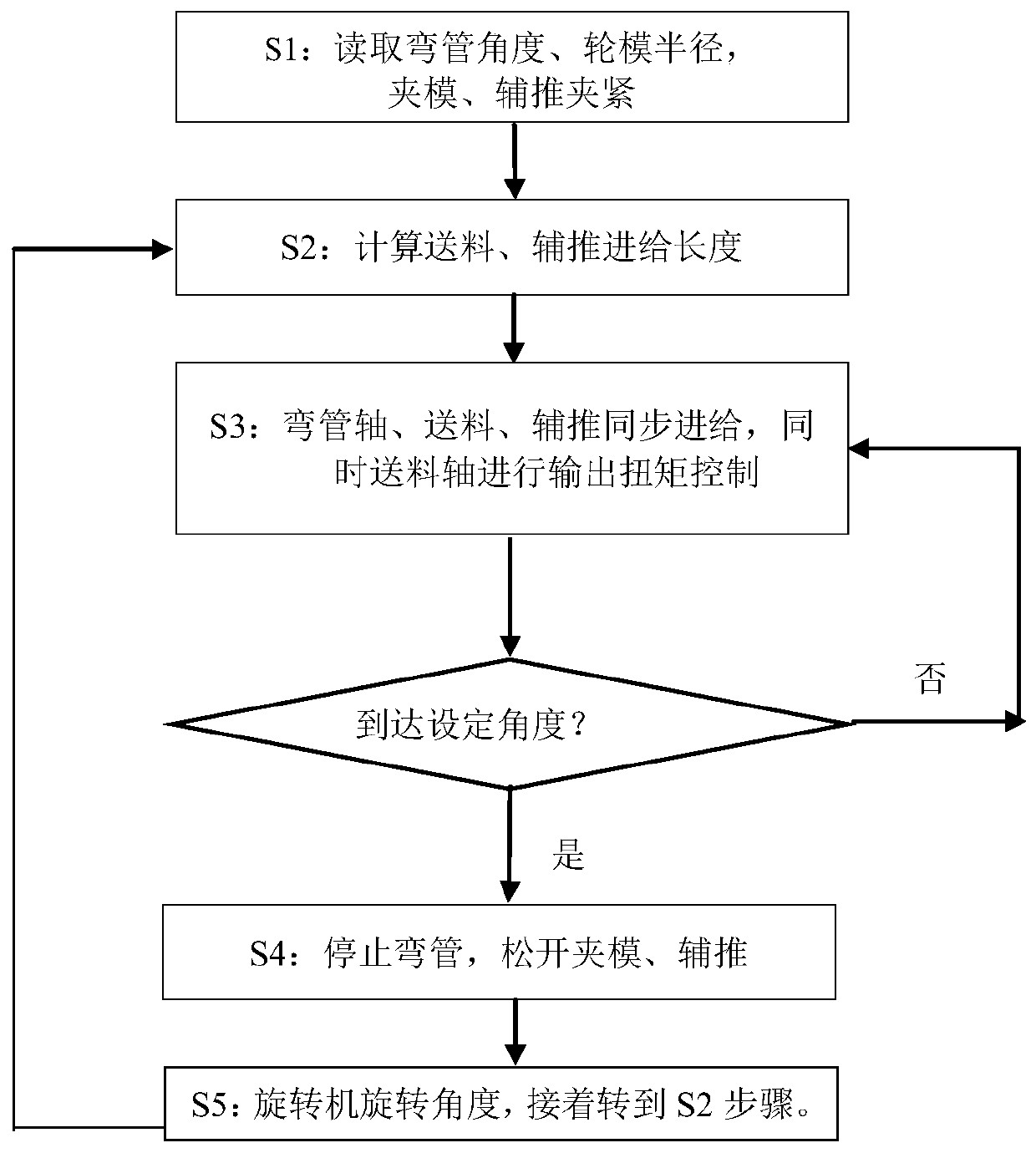
[0028] Such as figure 1 as shown, figure 1 It is a flow chart of Embodiment 1 of the present invention. Embodiment 1 of the present invention provides a method for controlling bending of a pipe bender after strong force, and the steps of the method are as follows:

[0029] S1: Read the angle of the elbow, clamp the mold, and push the auxiliary clamp;

[0030] The bending angle C, bending radius R and wheel mold radius are read by the pipe bending machine control system, and the pipe fittings are clamped by the clamping die and the auxiliary push shaft after loading;

[0031] S2: Calculate the feeding length and auxiliary feeding length;

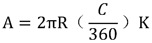
[0032] According to the elbow bending radius R and bending angle C technical parameters read by S1, the feeding feed length Y and auxiliary feed length F are calculated; the calculation method is as follows:

[0033] Known: bending radius R, bending angle C, coefficient K ranges from 0.8 to 1.2;

[0034] Suppose: the feeding length is Y, ...

Embodiment 2

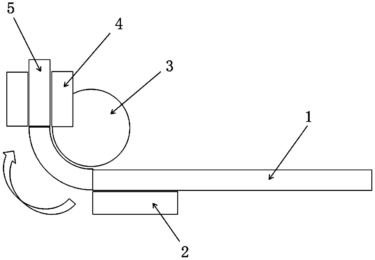
[0047] Such as figure 2 As shown, Embodiment 2 of the present invention also proposes a post-bend boost control system. The control system uses the powerful post-bend tube bend control method of the above-mentioned Embodiment 1 to achieve 1.5D small bending To meet the production requirements of curved pipes with a radius, the control system includes feeding shaft 1, auxiliary pushing shaft 2, wheel mold 3 and clamping die 4. One end of the pipe fitting 5 is clamped by the feeding shaft 1, and the other end is clamped by the clamping die 4. The auxiliary pushing shaft The shaft 2 is arranged outside the middle part of the pipe fitting 5, and the auxiliary pushing shaft 2 is close to the pipe fitting 5, and the figure 2 The direction of the arrow in the figure is the direction of the bent pipe, which is only for illustration and does not limit the present invention.

[0048] Through the implementation of Embodiment 2 and Embodiment 1, compared with the traditional bending mo...


PUM


Abstract

The invention discloses a strong rear propelling tube bending control method of a tube bending machine and a system, and belongs to the technical field of bent tube production control. The method comprises the steps that: S1: a tube bending angle is read, and a clamp die and an auxiliary pusher clamp materials; S2: the feeding lengths of a material supplying device and the auxiliary pusher are calculated; S3: synchronous feeding of a tube bending shaft, the material supplying device and the auxiliary pusher is carried out and output torque control over a material supplying shaft is conducted;S4: tube bending ceases, and the clamp die and the auxiliary pusher are loosened; and S5: a rotating mechanism rotates by a processing angle to conduct next tube bending processing, and step S2 is resumed. The system comprises the material supplying shaft, an auxiliary pushing shaft, a wheel mold, and the clamp die; a tube is clamped by the material supplying shaft and the clamp die; and the auxiliary pushing shaft is closely against the tube. According to the method and the system, the technical requirement that a tube is bent by a small bending radius of less than 1.5D can be met; differentdata are input for different radiuses, and then the system can automatically calculate a propelling route and a propelling torque; requirements of vehicle exhaust pipes, air conditioning pipes and special aeronautic tubes can be met; and the mechanical structure is simple, technical modification can be conveniently performed by equipment manufacturers and the universality is high.

Description

technical field [0001] The invention relates to the technical field of pipe bending production control, and in particular to a method and system for controlling a pipe bending machine after a strong boost push. Background technique [0002] Pipe bending machine is the main equipment for pipe bending and forming. It is widely used in industries such as automobile, motorcycle, chemical industry, furniture, aerospace and military industry. Higher and higher, it is required to have a greater breakthrough in adaptability, efficiency and precision, especially in industries such as ships, automobiles, transportation energy, aerospace, military industry, etc., which require high-precision automatic pipe benders. In the process of realizing the present invention Among them, the applicant found that there are at least the following problems in the existing technology: the traditional CNC pipe bending machine generally has a minimum bending radius of 1.5 times D when designing the tech...

Claims


Application Information

Patent Timeline
IPC IPC(8): B21D7/12B21D7/022
CPCB21D7/022B21D7/12
Inventor 温惠裕
Owner 苏州良裕科技有限公司
Why Eureka
Try Eureka