
Chuck structure for rapidly clamping shaft workpieces

A shaft workpiece and chuck structure technology, applied in the field of machinery, can solve the problems affecting the processing efficiency and processing accuracy, the workpiece is easy to loosen, and the processing efficiency is greatly affected, and achieves high firmness and coaxiality, reliable clamping, Efficient effect

Pending Publication Date: 2020-07-10
HUBEI UNIV OF SCI & TECH
View PDF0 Cites 5 Cited by
  • Summary
  • Abstract
  • Description
  • Claims
  • Application Information

AI Technical Summary

Problems solved by technology

[0002] During the processing of shaft workpieces, the workpiece needs to be clamped first. The clamping accuracy has a great influence on the machining accuracy, and the clamping efficiency has a great influence on the processing efficiency. The existing clamping tools for shaft workpieces are generally It is all realized by adjusting the clamping gap with multiple sliding calipers, and then fixing the adjusted calipers. However, the workpiece is easy to relax under the action of vibration and non-axial external force during processing, which seriously affects the processing efficiency and Precision

Method used


Image

  • Chuck structure for rapidly clamping shaft workpieces
  • Chuck structure for rapidly clamping shaft workpieces

Examples


Embodiment Construction

[0015] The following are specific embodiments of the present invention and in conjunction with the accompanying drawings, the technical solutions of the present invention are further described, but the present invention is not limited to these embodiments.

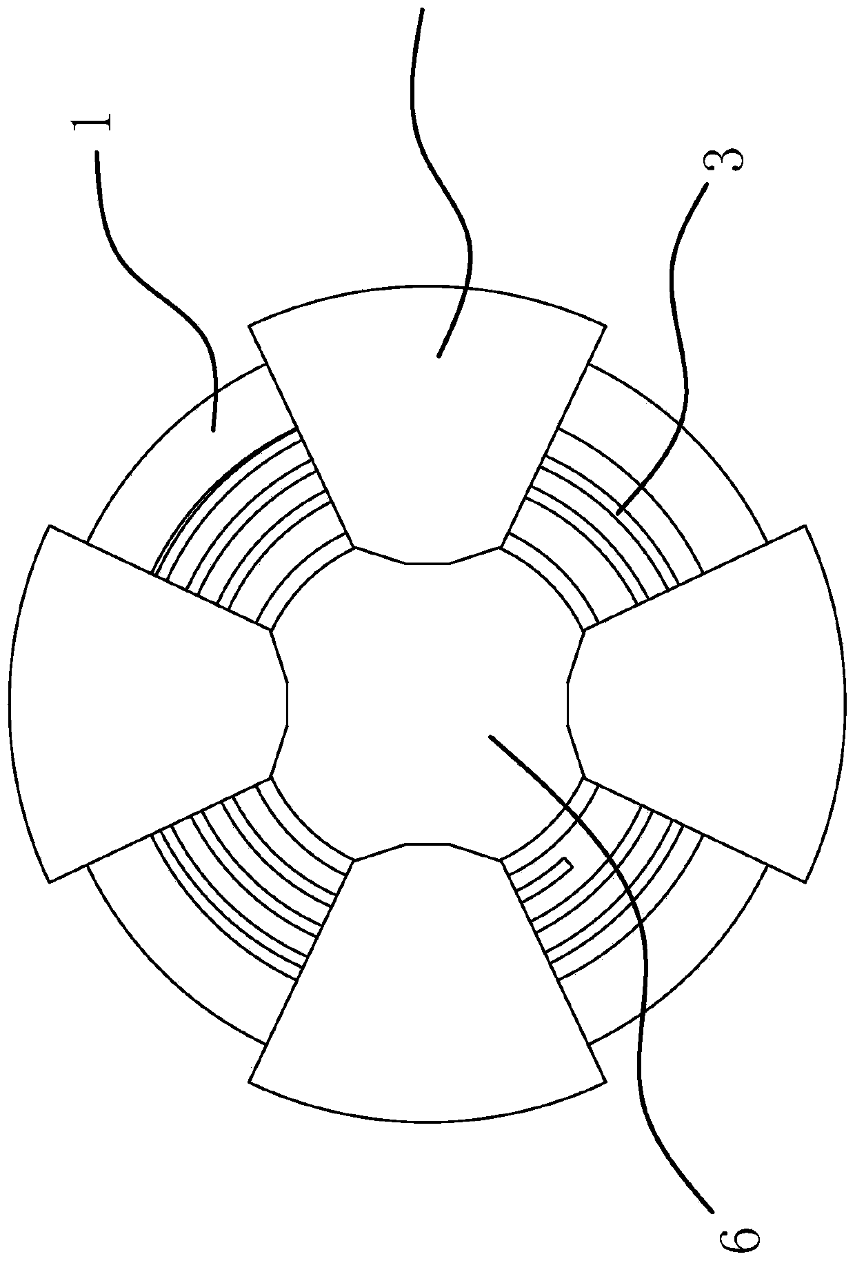
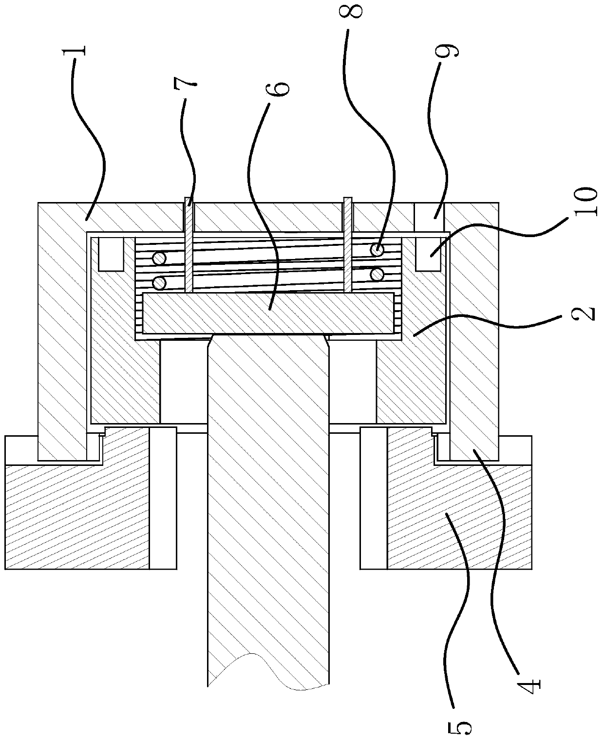
[0016] Such as figure 1 and figure 2 As shown, the chuck structure has a cylindrical body 1, one end of the body 1 is open, and a hollow sleeve 2 is arranged inside the body 1, the peripheral surface of the sleeve 2 is connected with the thread in the middle of the inner wall of the body 1, and the sleeve 2 is close to the body 1 There is a spiral groove 3 on the end surface of the opening end, and a number of guide blocks 4 are evenly arranged on the upper surface of the body 1 close to the end surface of the opening, and a caliper 5 is slidably connected to the guide block 4 along the radial direction of the body 1. The caliper 5 has a A number of threaded ribs corresponding to the spiral groove 3, the end of the sleev...


PUM


Abstract

The invention provides a chuck structure for rapidly clamping shaft workpieces, and belongs to the technical field of machinery. The chuck structure comprises a cylindrical body, one end of the body is opened, a hollow sleeve is arranged in the body, the circumferential surface of the sleeve is in threaded connection with the middle of the inner wall of the body, a spiral groove is formed in the end surface, close to the opened end of the body, of the sleeve, a plurality of guide blocks are uniformly arranged in the circumferential direction of the end surface, close to the opened end, of thebody, and a caliper is connected to the guide blocks in a sliding manner along the radial direction of the body. The caliper is provided with a plurality of thread convex ribs corresponding to the spiral grooves, the end, close to the bottom of the body, of the sleeve is provided with a step hole, the step hole is internally connected with a pressing block, a plurality of guide rods positioned atthe eccentric position of the pressing block are fixedly arranged on the pressing block, and the bottom of the body is provided with guide holes corresponding to the guide rods. The chuck structure has the advantages of being high in efficiency and the like.

Description

technical field [0001] The invention belongs to the technical field of machinery and relates to a chuck structure for quickly clamping shaft workpieces. Background technique [0002] During the processing of shaft workpieces, the workpiece needs to be clamped first. The clamping accuracy has a great influence on the machining accuracy, and the clamping efficiency has a great influence on the processing efficiency. The existing clamping tools for shaft workpieces are generally It is all realized by adjusting the clamping gap with multiple sliding calipers, and then fixing the adjusted calipers. However, the workpiece is easy to relax under the action of vibration and non-axial external force during processing, which seriously affects the processing efficiency and Precision. Contents of the invention [0003] The purpose of the present invention is to provide a chuck structure for quickly clamping shaft workpieces in view of the above-mentioned problems existing in the prio...

Claims


Application Information

Patent Timeline
Patent Type & Authority Applications(China)
IPC IPC(8): B23B31/02B23Q3/06
CPCB23B31/02B23Q3/062
Inventor 吴敏邹亮
Owner HUBEI UNIV OF SCI & TECH
Learn More