Textile hank yarn fluffing device
A technology of skein and loosening mechanism, which is applied in the direction of transportation and packaging, delivery of filamentous materials, and thin material processing, etc. It can solve the problems of single skein shaking work, general shaking effect, low work efficiency, etc. Artificial participation, improving the loosening effect and reducing the labor intensity
- Summary
- Abstract
- Description
- Claims
- Application Information
AI Technical Summary
Problems solved by technology
Method used
Image
Examples
specific Embodiment approach 1
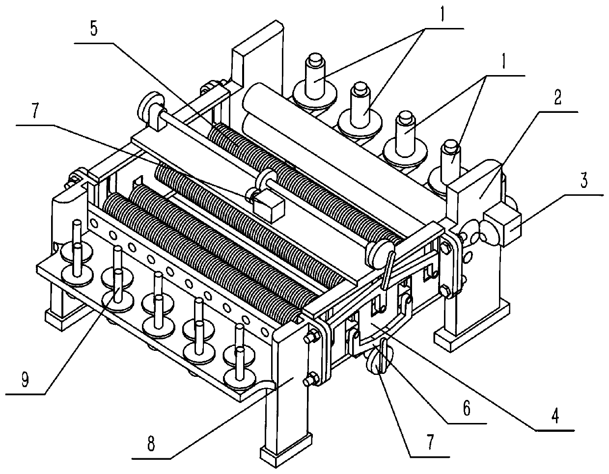
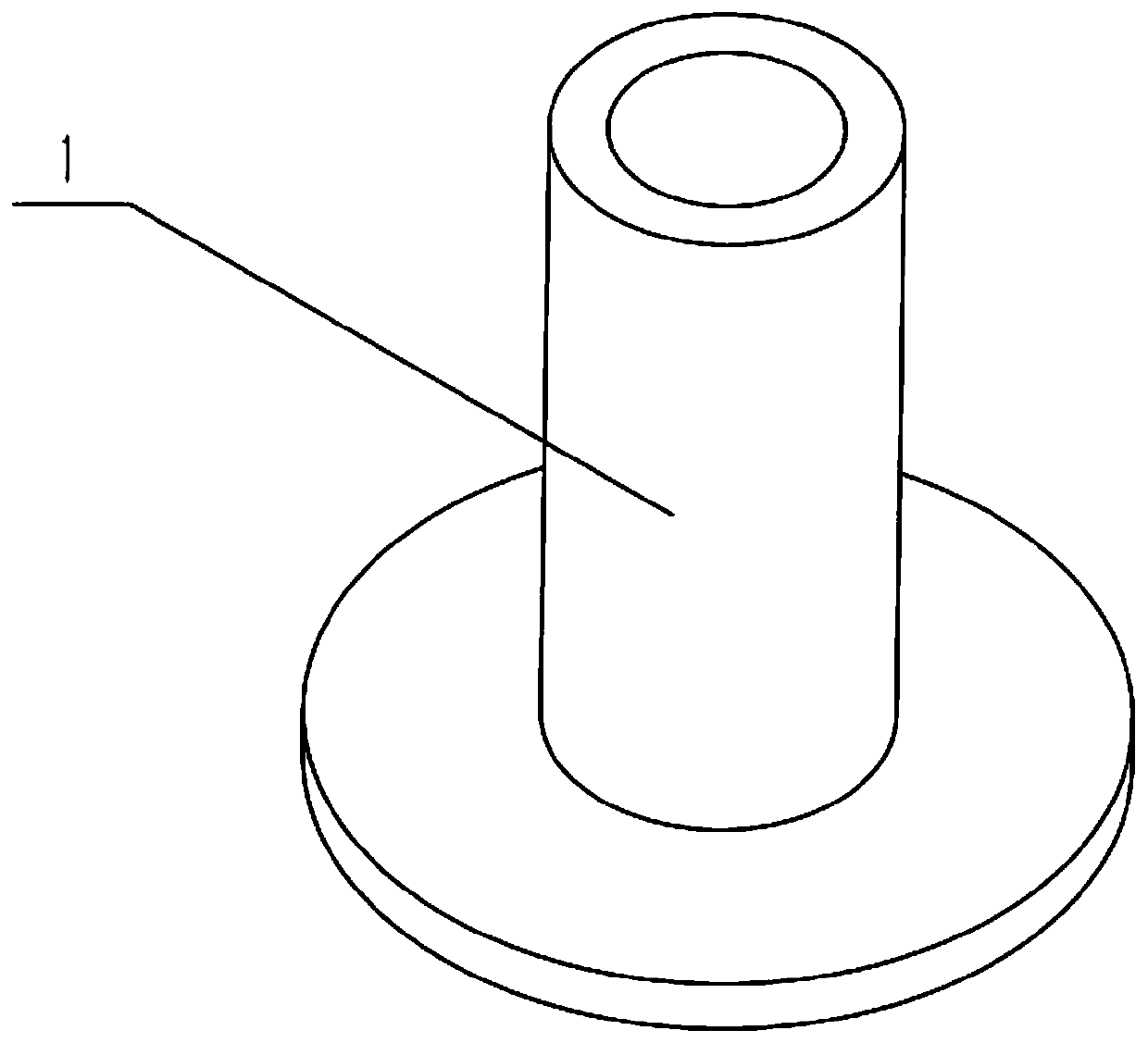
[0034] Combine below Figure 1-12 Description of this embodiment, a textile skein fluffing device, including a bobbin 1, the textile skein fluffing device also includes a support mechanism I2, a rolling mechanism 3, a bearing mechanism 4, a fluffing mechanism I5, a fluffing mechanism II6, drive mechanism 7, support mechanism II8 and wire take-up mechanism 9, the coiling tube 1 is provided with a plurality, and multiple coiling tubes 1 are evenly rotated and connected to the rear end of the supporting mechanism I2, and the rolling mechanism 3 is set At the front end of the support mechanism I2, the rolling mechanism 3 is fixedly connected to the front end of the support mechanism I2, the loosening mechanism I5 and the loosening mechanism II6 are respectively slidably connected to the upper and lower ends of the carrying mechanism 4, and the driving There are two mechanisms 7, and the two driving mechanisms 7 are respectively fixedly connected to the upper and lower ends of the ...
specific Embodiment approach 2
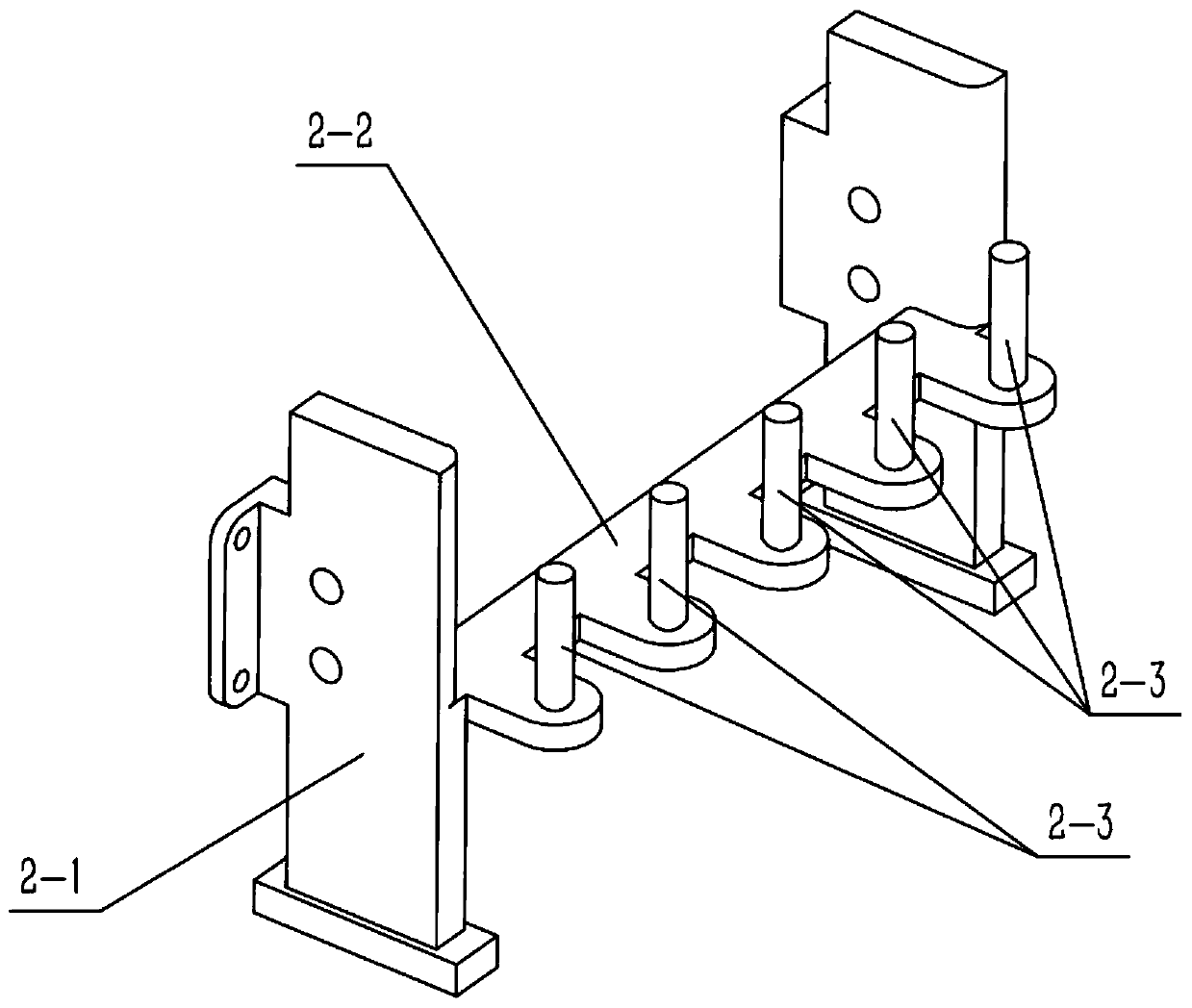
[0036] Combine below Figure 1-12 Describe this embodiment, this embodiment will further explain the first embodiment, the support mechanism I2 includes a support frame 2-1, a support plate 2-2 and a limit rod 2-3, the rear of the middle part of the support frame 2-1 A support plate 2-2 is provided at the end, and multiple limit rods 2-3 are provided, and multiple limit rods 2-3 are uniformly and fixedly connected to the rear end of the support plate 2-2, and multiple coil tubes 1 are respectively rotatably connected to a plurality of limit rods 2-3, the rolling mechanism 3 is arranged at the front end of the support frame 2-1, and the carrying mechanism 4 is fixedly connected to the front end of the support frame 2-1.
[0037] When the device is in use, multiple bundles of hank yarns are first set on multiple bobbin tubes 1, and then the bundles of hank yarns are pulled out respectively.
specific Embodiment approach 3
[0039] Combine below Figure 1-12 Describe this embodiment, this embodiment will further explain the second embodiment, the rolling mechanism 3 includes a motor I3-1, a bevel gear 3-2, a rolling roller 3-3 and a gear I3-4, the rolling mechanism 3 There are two pressing rollers 3-3, and the two rolling rollers 3-3 are rotatably connected to the front end of the support frame 2-1. There are two gears I3-4, and the two gears I3-4 are respectively fixed It is connected to the right end of the two rolling rollers 3-3, and the two gears I3-4 are meshed and connected to each other. There are two bevel gears 3-2. The pressure roller 3-3 is fixedly connected to the output shaft of the motor, and the motor I3-1 is fixedly connected to the left end of the support frame 2-1.
[0040] Start the motor Ⅰ3-1, the output shaft of the motor Ⅰ3-1 drives the rear bevel gear 3-2 to rotate, and the rear bevel gear 3-2 drives the right bevel gear 3-2 to rotate through gear meshing transmission, and...
PUM
 Abstract
Description
Claims
Application Information
 - R&D
- Intellectual Property
- Life Sciences
- Materials
- Tech Scout
- Unparalleled Data Quality
- Higher Quality Content
- 60% Fewer Hallucinations
Browse by: Latest US Patents, China's latest patents, Technical Efficacy Thesaurus, Application Domain, Technology Topic, Popular Technical Reports.
© 2025 PatSnap. All rights reserved.Legal|Privacy policy|Modern Slavery Act Transparency Statement|Sitemap|About US| Contact US: help@patsnap.com


