
A kind of rubber roller for Siro fancy yarn and its production method

A fancy yarn and siro technology, which is applied to the cots and production fields of siro fancy yarns, can solve the problems of difficulty in obtaining the expected drafting force, and the finished pattern is difficult to play an auxiliary role, and achieves the effect of increasing varieties.

Active Publication Date: 2021-08-24
JIANGNAN UNIV
View PDF9 Cites 0 Cited by
  • Summary
  • Abstract
  • Description
  • Claims
  • Application Information

AI Technical Summary

Problems solved by technology

However, in the above-mentioned structure, the groove is arranged in a ring shape. During the actual use of the groove, because the degree of depression is the same everywhere, and the roving is embedded in the groove, it is difficult to obtain the expected draft force. Therefore, the groove can only It plays the role of limit, and it is difficult to play an auxiliary role in the finished pattern

Method used

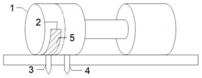
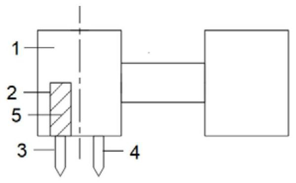
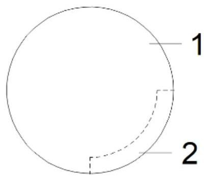

Image

  • A kind of rubber roller for Siro fancy yarn and its production method
  • A kind of rubber roller for Siro fancy yarn and its production method
  • A kind of rubber roller for Siro fancy yarn and its production method

Examples


Embodiment 1

[0032] Such as Figure 1-3 As shown, a rubber roller for Siro fancy yarn includes a roller roller body 1, and the roller roller body 1 is set as three coaxially connected cylinders, which are respectively a cylinder with a larger diameter at both ends and a cylinder connecting the two ends. A cylinder is a cylindrical rod with a smaller diameter. A first groove 2 is provided on the outer surface of the cylinder at one end of the roller body 1, and the first groove 2 in this embodiment is a rectangular groove. With half the axis of the cylindrical end as the boundary, the first groove 2 is arranged on the side of the cylinder away from the cylindrical rod; let the half of the axis of the cylindrical end, that is, the circumference of the middle position of the cylindrical end, be the reference, the first groove 2 The distance between a groove 2 and the reference is 2-3 mm, and 2.5 mm is used in this embodiment. The groove width range of the first groove 2 is 5.5-6.5mm, and th...

Embodiment 2

[0037] The difference from Example 1 is that, as Figure 8 As shown, the arc at the groove bottom of the groove 2 is set coaxially with the outer circle of the roller body 1, and the drafting teeth 5 are set as several sawtooths 52 with the same shape and size. The projection on the top is pointed, and the serrations 52 are arranged in a circular array at the bottom of the groove 2 , and the tooth roots of the serrations 52 are in contact with the bottom of the groove.

Embodiment 3

[0039] The difference from Embodiment 1 or 2 or 3 is that the roller body 1 can be engraved with grooves 2 on each spindle roller body 1 according to the actual design and color requirements, and the number of grooves 2 in each row is 0- 4, the total number of grooves 2 is at least 1, the difference from embodiment 1 is that, as Figure 4-6 As shown, in the present embodiment, two grooves 2 are engraved on a roller body 1 of a spindle.

[0040] The two grooves 2 are on the outer circular surface of the same cylindrical end, and are located on both sides of the center line of the outer circular surface of the cylindrical end, and the distance between the two grooves 2 and the center line is 2-3mm. In this embodiment The selected node value of the distance is 2.5 mm, that is, the distance between two rows of grooves 2 is 4-6 mm, which is 5 mm in this embodiment. The groove 2 on the left side and the groove 2 on the right side are distributed in a staggered manner. The groove wi...


PUM


Abstract

The invention discloses a rubber roller for a Siro fancy yarn and a production method thereof, and relates to the modification of a spinning frame device. The spinning frame device is a rear roller rubber roller. The back roller rubber roller is engraved with grooves. The Siro spinning production process is adopted on the spinning frame. When two rovings are fed into the rear roller of the spinning frame, when the rear roller rubber roller is rotating, when the groove turns to the bottom, the rear roller rubber roller has no holding force on the roving. , the draft ratio in the back zone is reduced to 1, and when the groove leaves the bottom, the back roller cots have a grip on the roving, and the roving is normally drafted in the back zone. Thus the roving is fed to the rear roller and is drawn intermittently in the rear area, and a new type of siro fancy yarn is obtained. The new-style siro fancy yarn has regular thickness changes in the longitudinal direction, presenting regular thickness changes of the first roving or the second roving color, and the color is determined according to the position and number of grooves, and its fabric products have a unique style, color levels Features such as strong sense.

Description

technical field [0001] The invention relates to a rubber roller for a siro fancy yarn and a production method, belonging to the technical field of textiles. Background technique [0002] Siro spinning is a method of directly spinning yarns with a similar strand structure on the ring spinning frame. In the separated state of the root strands, the front roller outputs a certain length and merges them, and then twists through the same spindle to form a double-strand yarn. [0003] Fancy yarn refers to the use of special raw materials, special processes or special equipment to process fibers or yarns in the spinning process to obtain yarns with special structure or appearance effects. Fancy yarn has the characteristics of strong three-dimensional effect and rich colors, and its fabric style is unique, which meets the needs of consumers in pursuit of fashion and individuality, and has increasingly become a popular trend. [0004] In the prior art, when it is necessary to draft ...

Claims


Application Information

Patent Timeline
Patent Type & Authority Patents(China)
IPC IPC(8): D01H5/74D01H5/78
CPCD01H5/74D01H5/78
Inventor 阮丽刘基宏江红霞孙荣基
Owner JIANGNAN UNIV
Learn More