Locking device

A technology of locking device and pawl, which is applied in the direction of seat belts, pivot connections, life-saving equipment, etc., can solve problems such as insufficient safety performance, and achieve the effect of improving safety and facilitating maintenance

Pending Publication Date: 2020-07-10
河南省有限元游乐设计研究院有限公司
View PDF3 Cites 2 Cited by
  • Summary
  • Abstract
  • Description
  • Claims
  • Application Information

AI Technical Summary

Problems solved by technology

[0005] The object of the present invention is to provide a locking device aimed at solving the problem of insufficient safety performance of the locking device for amusement equipment in the prior art

Method used


Image

  • Locking device
  • Locking device
  • Locking device

Examples


Embodiment Construction

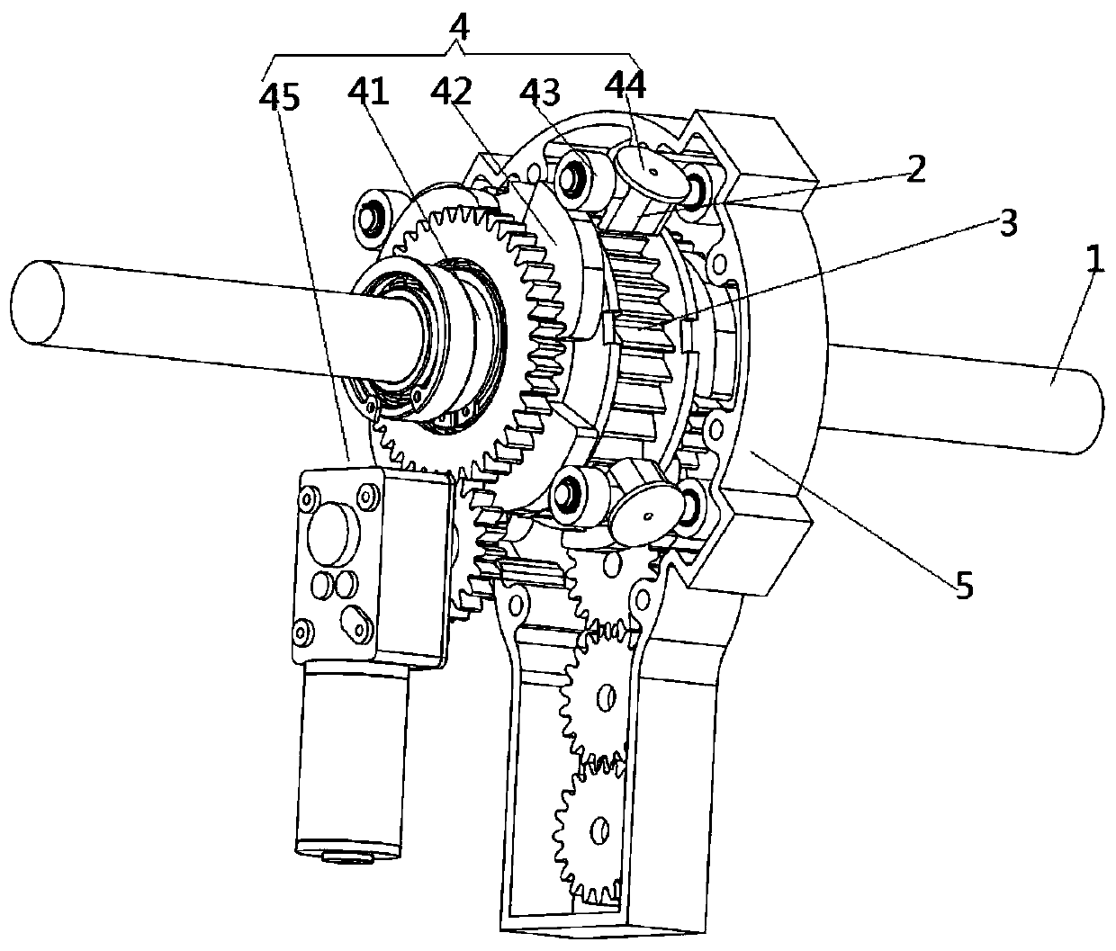
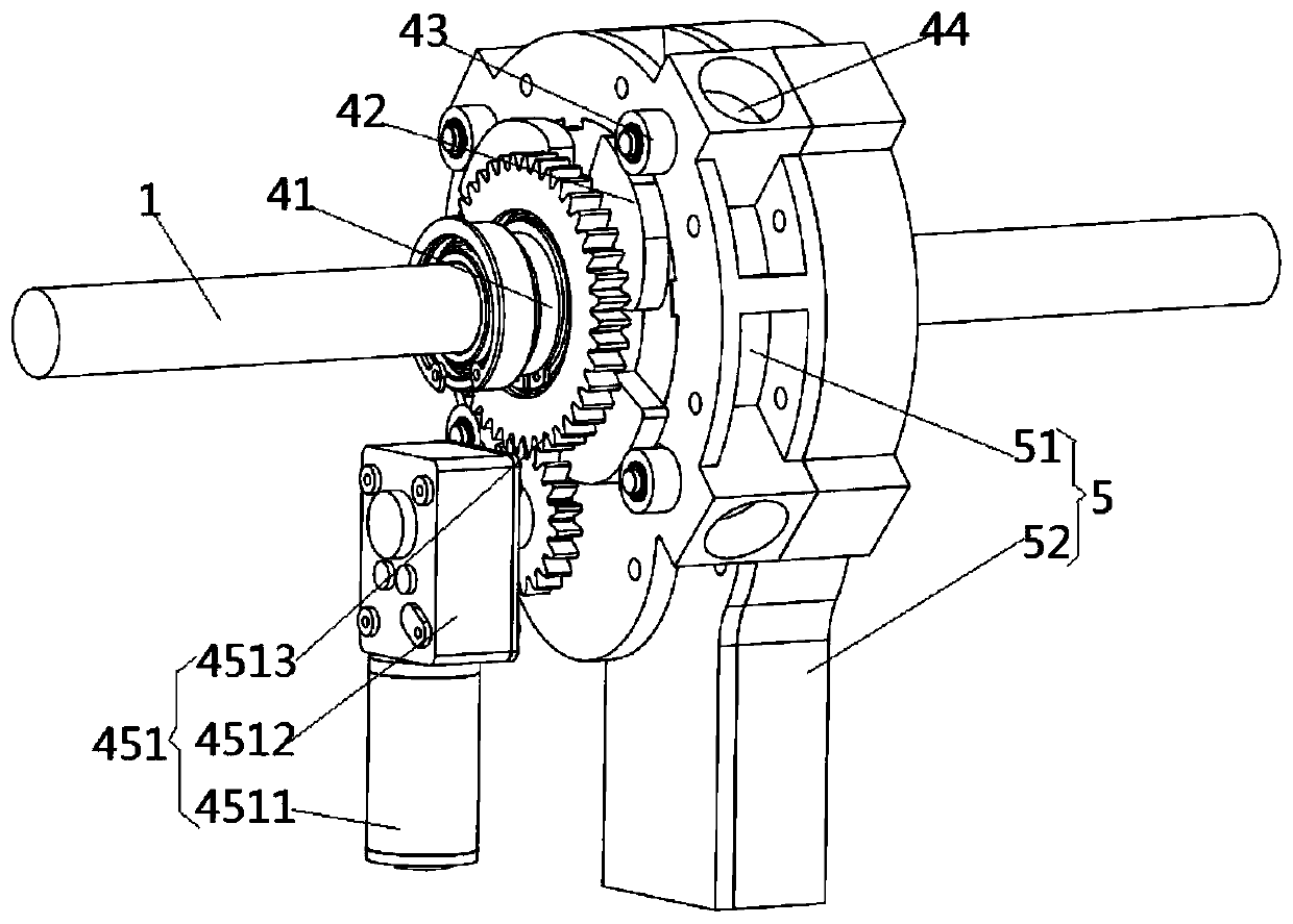
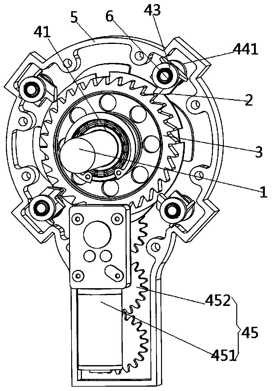
[0033] The specific embodiments of the present invention will be further described below in conjunction with the accompanying drawings.

[0034] Such as Figure 1-15 As shown, a locking device includes a ratchet 3 fixedly installed on the main shaft 1; at least two pawls 2 inserted into the tooth gap of the ratchet 3; at least two pawls 2 for synchronous driving to enter or disengage The ratchet driving mechanism 4 of the tooth gap of the ratchet 3; at least two ratchets 2 are inserted into the tooth gap sequentially along the circumferential direction of the ratchet 3. The depth is from deep to shallow, and the depth inserted into the tooth gap is from deep to deep. The distance between the tooth surfaces of the shallow pawl 2 and the ratchet wheel 3 in the same direction of rotation increases successively.

[0035]In a specific embodiment of the present invention, since a plurality of pawls 2 are sequentially inserted into the tooth gap from deep to shallow, and these pawls...


PUM


Abstract

The invention provides a locking device, and relates to the technical field of entertainment equipment. The locking device comprises a ratchet wheel fixedly mounted on a main shaft, at least two ratchet pawls inserted into tooth space of the ratchet wheel, and a ratchet pawl driving mechanism used for synchronously driving the at least two ratchet pawls to enter the tooth space of the ratchet wheel or separate from the tooth space of the ratchet wheel; the depth of the at least two ratchet pawls inserted into the tooth space from deep to shallow in the circumferential direction of the ratchetwheel, and the space between the ratchet pawls with the depth inserted into the tooth space from deep to shallow and a tooth surface in the same rotating direction of the ratchet wheel is increased insequence; after part of the ratchet pawls or teeth of the ratchet wheel causes the failures, such as breakage, the ratchet wheel is limited again by the other part of the ratchet pawls in time; the ratchet wheel can be limited repeatedly, so that the locking device has a multi-stage locking effect; compared with a single-stage locking mechanism adopted in the prior art, the safety of the lockingdevice is greatly improved to a great extent; and moreover, remediation can be performed in time after part ratchet pawls or the teeth of the ratchet wheel fail, which facilitates maintenance, replacement and the like of the locking device by working personnel after an event.

Description

technical field [0001] The invention relates to the technical field of amusement equipment, in particular to a locking device. Background technique [0002] The safety of amusement facilities undoubtedly takes precedence over the amusement of amusement facilities, and safety seats are installed in some large amusement facilities. At present, the safety seat pressure bar locking device for amusement facilities in the prior art usually adopts a pawl type locking device, including a pressure bar assembly and a locking assembly, and the locking assembly includes a ratchet strip and a pawl, wherein the pressure bar The component and the spine are hinged with connecting pins. When in use, the pressing bar assembly is opened, and the ratchet bar is driven to move linearly through the connecting pin, so that the ratchet pawl engages the ratchet bar to realize locking. [0003] After searching, it was found that a Chinese patent with the authorized announcement number CN205055248U ...

Claims


Application Information

Patent Timeline
Patent Type & Authority Applications(China)
IPC IPC(8): F16C11/10A62B35/00
CPCA62B35/00F16C11/10
Inventor 时振曹祥坤赵九峰薛飞
Owner 河南省有限元游乐设计研究院有限公司
Why Eureka
Try Eureka