
Automatic transfer switching equipment

A technology of automatic transfer switch and micro switch, which is applied in the direction of electric switches, circuits, electrical components, etc., can solve the problems of inability to accurately reflect the working status of automatic transfer switch electrical appliances, potential safety hazards, and inaccurate feedback of contacts, and achieve simple structure , high reliability and easy assembly

Pending Publication Date: 2020-07-10
RADIN ELECTRIC TECH
View PDF0 Cites 0 Cited by
  • Summary
  • Abstract
  • Description
  • Claims
  • Application Information

AI Technical Summary

Problems solved by technology

Automatic transfer switch electrical appliances have the positions of "common power supply", "standby power supply" and "two-way disconnection". The state of “on” and “two-way disconnected”, the existing micro switch is generally set on the operation side of the automatic transfer switch appliance, and the micro switch is directly triggered by the handle and the motor to feedback the working state. This method cannot accurately reflect the automatic In the working state of the contact side of the transfer switch appliance, when a fault occurs inside the automatic transfer switch appliance and the contacts cannot be closed accurately, there is no accurate feedback, and there is a certain potential safety hazard

Method used


Image

  • Automatic transfer switching equipment
  • Automatic transfer switching equipment
  • Automatic transfer switching equipment

Examples


Embodiment Construction

[0025] The present invention will be further described below in conjunction with the accompanying drawings.

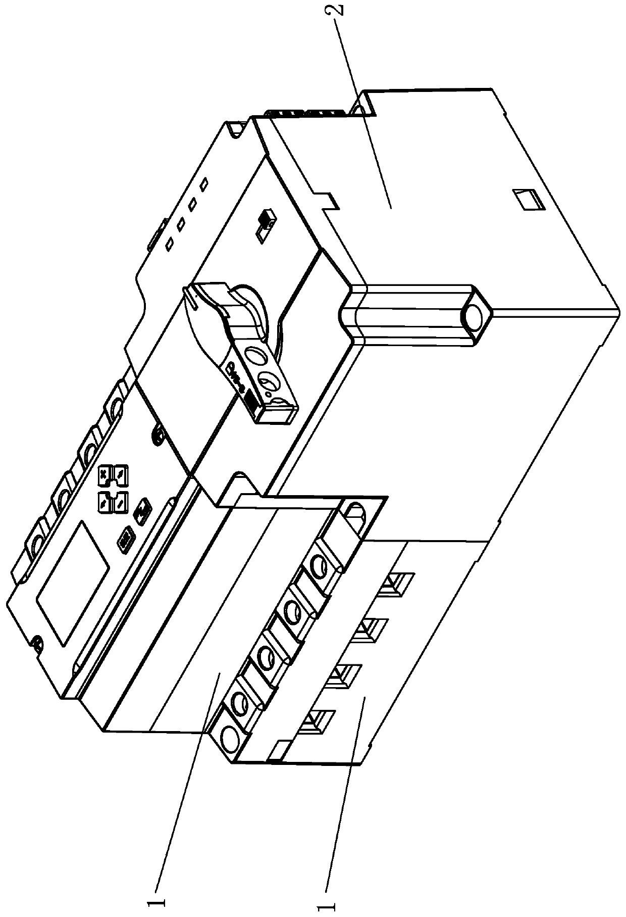
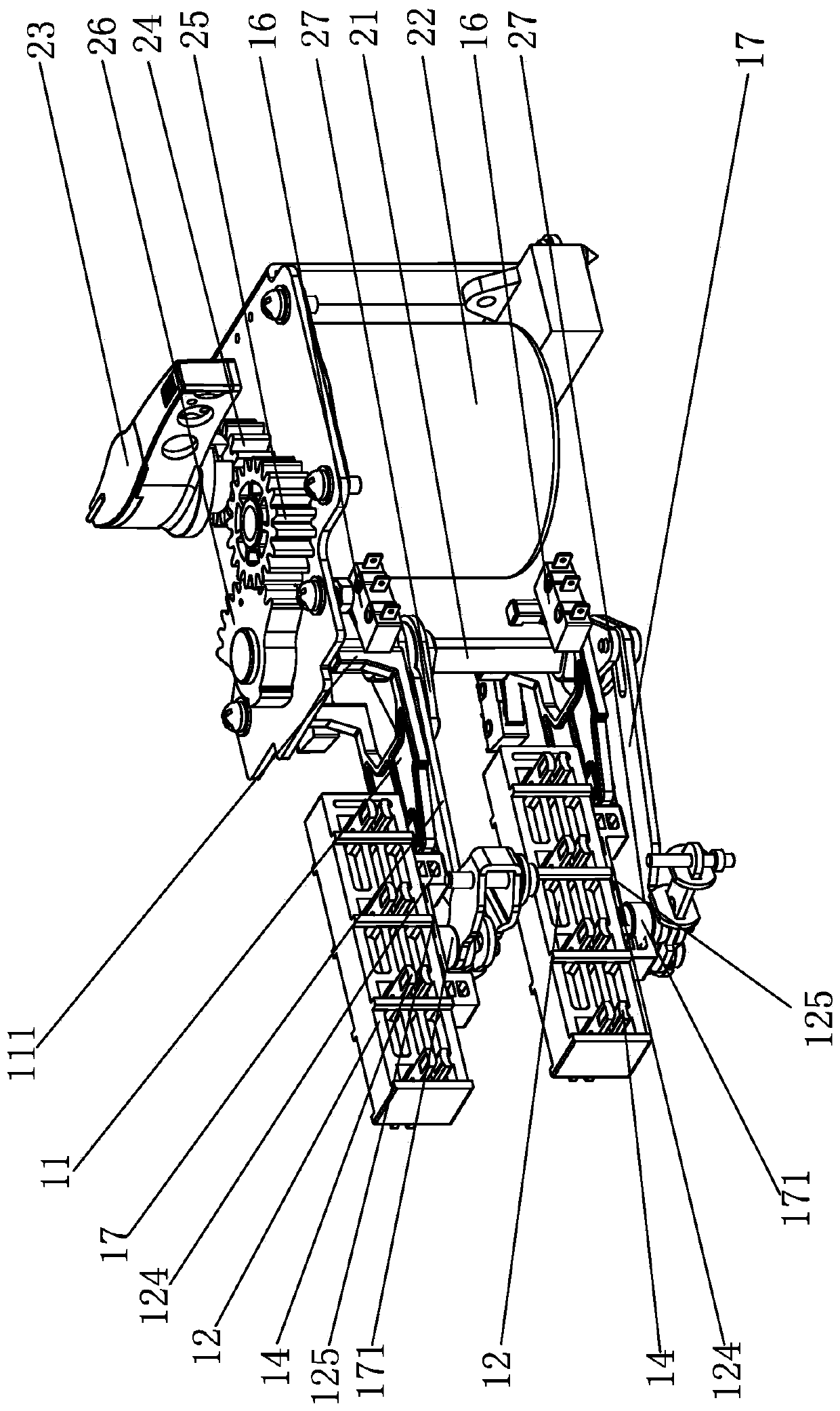
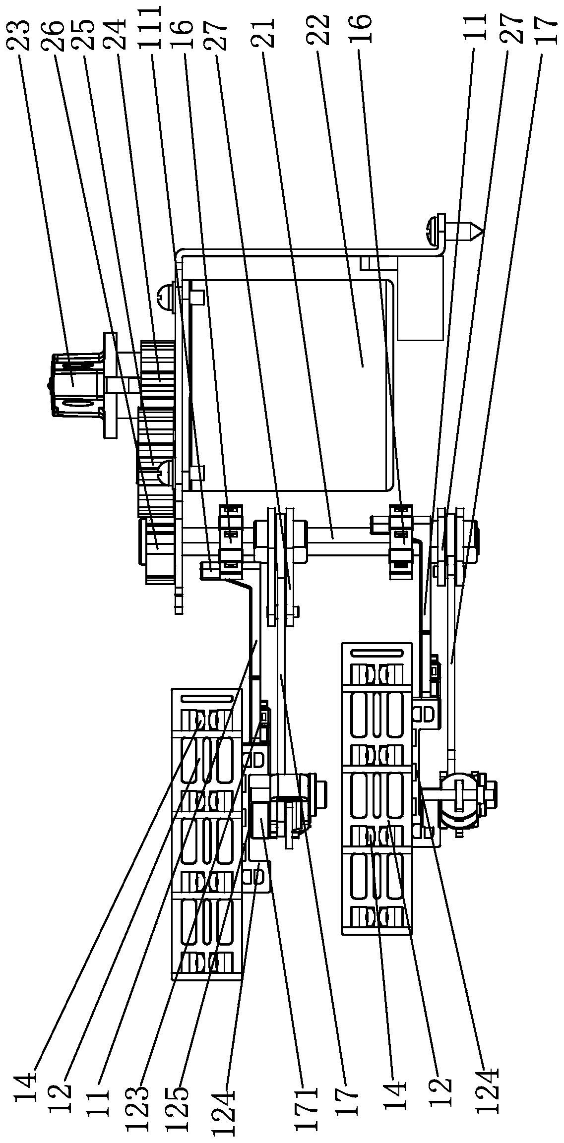
[0026] Such as Figure 1-Figure 5 As shown, the specific embodiment of the present invention is an automatic transfer switch electrical appliance including an operating mechanism 2 and two groups of contact systems 1, the operating mechanism 2 includes a casing and a drive shaft 21, a motor 22, a handle 23, and a drive shaft arranged in the casing. Gear 24, transmission gear 25, driving gear 26, driving gear 24 and handle 23 are connected on the output shaft of motor 22, driving gear 24 is arranged between motor 22 and handle 23, driving gear 26 center is connected with drive shaft 21, transmission The gear 25 is connected between the driving gear 24 and the driving gear 26. The driving shaft 21 is a semi-shaft structure. The driving shaft 21 is provided with two sets of protruding driving pieces 27. The orientations of the two groups of driving pieces 27 are inconsist...


PUM


Abstract

The invention relates to automatic transfer switching equipment which comprises an operating mechanism and two groups of contact systems. The operating mechanism comprises a driving shaft. Each contact system comprises two groups of static contacts, a group of moving contacts, a moving contact support and a transmission rod, wherein the moving contacts are arranged in the moving contact support and move back and forth along with the moving contact support, a transmission seat is formed on the lower side of the moving contact support, a transmission groove is formed in the transmission seat, the transmission rod extends into the transmission groove to drive the moving contact support to move back and forth, the other end of the transmission rod is connected to the driving shaft in a linkagemode, a feedback support is arranged on the moving contact support and extends outwards, a micro switch is arranged on the outer side of the feedback support, and the feedback support can touch the micro switch when moving along with the moving contact support. The moving contact supports are directly connected with the feedback supports, the feedback supports are matched with the micro switchesto achieve accurate feedback of the positions of the moving contacts, the accuracy of feedback signals is improved, and feedback errors caused by the fact that the moving contacts break down and cannot move are avoided.

Description

technical field [0001] The invention relates to an automatic transfer switch electric appliance Background technique [0002] The automatic transfer switch is used in the two-way neutral point grounding power supply system to switch between the power supplies due to an abnormality in one power supply, so as to ensure the reliability and safety of its power supply. Automatic transfer switch electrical appliances have the positions of "common power supply", "standby power supply" and "two-way disconnection". The state of “on” and “two-way disconnected”, the existing micro switch is generally set on the operation side of the automatic transfer switch appliance, and the micro switch is directly triggered by the handle and the motor to feedback the working state. This method cannot accurately reflect the automatic In the working state of the contact side of the transfer switch electrical appliance, when a fault occurs inside the automatic transfer switch appliance but the contac...

Claims


Application Information

Patent Timeline
Patent Type & Authority Applications(China)
IPC IPC(8): H01H9/02H01H9/08H01H9/20
CPCH01H9/08H01H9/02H01H9/20
Inventor 银引森吴利军彭武忠
Owner RADIN ELECTRIC TECH
Learn More