Light-dimmer driving circuit

A dimming drive and circuit technology, applied in the field of dimming, can solve the problems of limited dimming range of pure analog circuits, reduce power factor value, destroy sine wave waveform, etc., achieve flicker-free dimming and constant current output, and ensure safety and stability, and improve the effect of constant current accuracy

A dimming drive and circuit technology, applied in the field of dimming, can solve the problems of limited dimming range of pure analog circuits, reduce power factor value, destroy sine wave waveform, etc., achieve flicker-free dimming and constant current output, and ensure safety and stability, and improve the effect of constant current accuracy

CN103096586AInactive Publication Date: 2013-05-08GUANGDONG ZONOPO INTELLIGENT TECH

Image

  • Light-dimmer driving circuit
  • Light-dimmer driving circuit

Examples


Embodiment

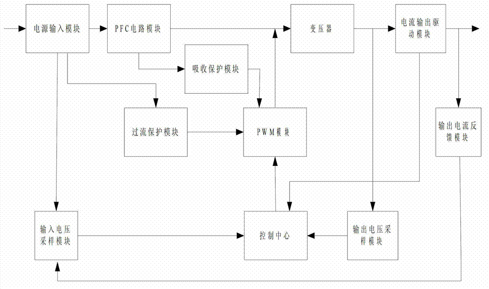
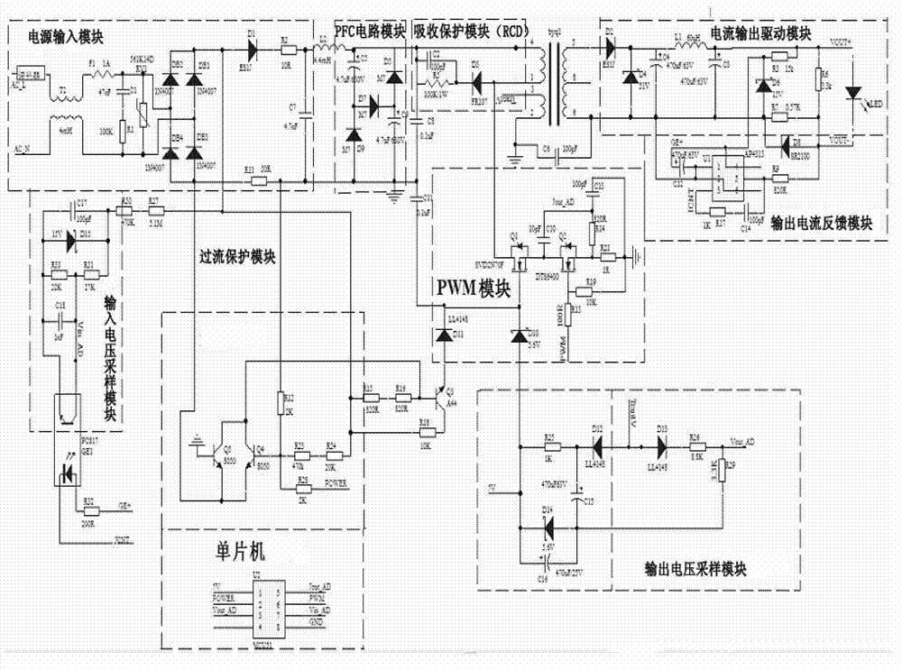
[0031] like figure 1 As shown, a dimming drive circuit includes a power input module mainly used to rectify and filter an input voltage signal, a PFC circuit module used to adjust the power factor of the dimming drive circuit, and used to protect the switch tube in the PWM module. The absorption protection module is used for the transformer to step down the voltage signal, the current output drive module that drives the current output according to the transformed voltage signal, and the PWM module that controls the output power of the current output drive module according to the control signal of the control center. The PWM module outputs a PWM signal, controls the overcurrent protection module of the PWM module to turn on or off through the input current of the power input module, and feeds the output current back to the output current feedback module of the input voltage sampling module to sample the input voltage signal, and then The input voltage sampling signal is input t...


PUM


Abstract

The invention relates to a light-dimmer driving circuit. The light-dimmer driving circuit comprises a power supply input module, a transformer, a current output driving module, a pulse width modulation (PWM) module, an input voltage sampling module, an output voltage sampling module and a control center, wherein the power supply input module is mainly used for rectification and filtering of an input voltage signal, the transformer is used for voltage reduction of the voltage signal output by the power supply input module, the current output driving module is used for driving of current output according to the voltage signal which is transformed, the PWM module is used for adjusting output power of the current output driving module according to a control signal in the control center, the input voltage sampling module is used for sampling of the input voltage signal and transmitting the input voltage signal to the control center, the output voltage sampling module is used for sampling of output voltage and transmitting the output voltage to the control center, and the control center is used for controlling a PWM signal according to an input voltage sampling signal, an output voltage sampling signal and an input current signal. According to the light-dimmer driving circuit, due to the fact that the control center is used for controlling the PWM signal according to the input voltage sampling signal, the output voltage sampling signal and the input current signal, the output power of the current output driving module is enabled to change evenly, flicker-free light adjusting is achieved, constant current output is achieved, and range of the light adjusting is wide.

Description

technical field [0001] The invention relates to the field of dimming, in particular to a dimming driving circuit, which is especially suitable for dimming driving of LED lamps. Background technique [0002] With the increasingly serious energy crisis around the world, low carbon and environmental protection have become the focus issues, more and more people pay attention, and lighting as a major aspect of power and energy consumption has also attracted much attention. As a new concept solid light source, LED is recognized as one of the most promising new technologies in the world in the 21st century because of its remarkable advantages of energy saving, environmental protection, long life, no pollution, easy control and high efficiency. [0003] The lifespan of LED lamps depends largely on the performance of the driving power supply. The energy-saving performance of the LED lighting system is determined by the power consumption of the LED chip and the efficiency of the power...

Claims


Application Information

Patent Timeline
08 May 2013
Publication
CN103096586A
IPC
H05B37/02
Inventors
刘达樊; 蓝学明