Mobile phone finger frame with bracket, finger frame shell and finger frame mobile phone
A mobile phone shell and mobile phone technology, applied in the direction of telephone structure, telephone communication, electrical components, etc., can solve the problem of inconvenient use of the desktop, and achieve the effect of small size, simple structure, and convenient mobile phone life
- Summary
- Abstract
- Description
- Claims
- Application Information
AI Technical Summary
Problems solved by technology
Method used
Image

Examples
Embodiment 1
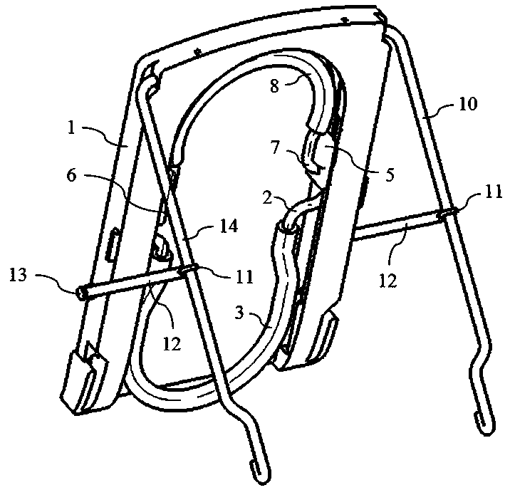
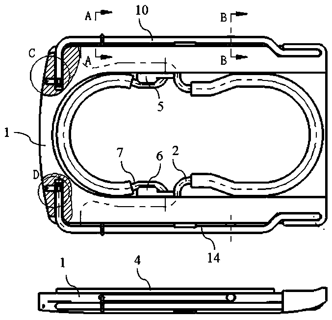
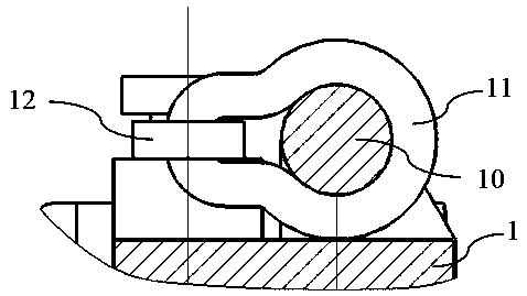
[0050] See Figure 1 to Figure 10 In this embodiment, the mobile phone finger holder with a bracket includes a base body 1, a finger bar 2, a first soft layer 3, an adhesive layer 4, a first sliding seat 5, a second sliding seat 6, a finger ring 7, a second soft layer 8, and a A rod 10, a ring rod 11, a tie rod 12, a first pin 13 and a first positioning nail 15.
[0051] The base 1 includes a first side surface 101, a second side surface 102, a left end surface 103, and a right end surface 104; a first concave surface 105 is provided on the inner side of the first side surface 101 near the left end surface 103; a first concave surface 105 is provided on the first concave surface 105 Rotating hole 107; A first positioning hole 109 is provided on the periphery of the first turning hole 107. In this embodiment, the first positioning hole 109 is provided on the left end surface 103; a first locking position 111 is provided on the first side surface 101;
[0052] The first rod 10 inclu...
Embodiment 2
[0066] See Picture 11 with Picture 12 , Including base 1, finger rod 2, first soft layer 3, adhesive layer 4, first sliding seat 5, second sliding seat 6, finger ring 7, second soft layer 8, ring rod 11, tie rod 12, first pin 轴13、third strut 17.
[0067] The third support rod 17 is composed of a first guide rod 1701, a second guide rod 1702, a first bending rod 1703, a second bending rod 1704, a cross rod 1705, a first shaft 1706, and a second shaft 1707; the first guide rod 1701 , The second guide rod 1702, the first shaft 1706, and the second shaft 1707 are coplanar; the first shaft 1706 is coaxial with the second shaft 1707; the cross bar 1705 is parallel to the first shaft 1706 or the second shaft 1707;
[0068] The first rotation shaft 1706 of the third support rod 17 is rotatably connected with the first rotation hole 107 of the base body 1; the second rotation shaft 1707 of the third support rod 17 is rotatably connected with the second rotation hole 108 of the base body 1;...
Embodiment 3
[0072] See Figure 13 , Including base 1, finger bar 2, first soft layer 3, adhesive layer 4, first sliding seat 5, second sliding seat 6, finger ring 7, second soft layer 8, mobile phone case or mobile phone back cover 9, first Support rod 10, ring rod 11, pull rod 12, first pin 13, first positioning nail 15; mobile phone case or mobile phone back cover 9 and base body 1 are formed or fixedly connected at one time;
[0073] Further, it also includes a second supporting rod 14 and a second positioning nail 16; the rotating rod of the second supporting rod 14 is rotatably connected in the second rotating hole 108 of the base 1; The positioning hole 110 is fixedly connected and extends into the slot of the second support rod 14 to be slidably connected
[0074] The rest is the same as the first embodiment, and will not be repeated.
PUM
 Abstract
Description
Claims
Application Information
 - R&D Engineer
- R&D Manager
- IP Professional
- Industry Leading Data Capabilities
- Powerful AI technology
- Patent DNA Extraction
Browse by: Latest US Patents, China's latest patents, Technical Efficacy Thesaurus, Application Domain, Technology Topic.
© 2024 PatSnap. All rights reserved.Legal|Privacy policy|Modern Slavery Act Transparency Statement|Sitemap