Quick positioning structure for riveting of thin cooling fins and thin cover plate

A heat dissipation fin and positioning structure technology, applied in the direction of heat exchanger fixation, heat exchange equipment, heat exchanger shell, etc., can solve the problem of time-consuming and laborious, the convex part is easy to come out of the riveting hole, and the thin heat dissipation fin is easy to left and right. Problems such as deflection can be solved to achieve the effect of improving quality and avoiding left and right deflection

Active Publication Date: 2021-05-18
DONG GUAN HAN XU HARDWARE & PLASTIC TECH CO LTD
View PDF9 Cites 0 Cited by
  • Summary
  • Abstract
  • Description
  • Claims
  • Application Information

AI Technical Summary

Problems solved by technology

However, this method cannot be positioned before and during assembly, and it is difficult to achieve rapid alignment installation between each convex part and each riveting hole, which is time-consuming and laborious. It is easy to swing left and right, and the convex part is easy to come out of the riveting hole, thus affecting the quality of riveting installation

Method used


Image

  • Quick positioning structure for riveting of thin cooling fins and thin cover plate
  • Quick positioning structure for riveting of thin cooling fins and thin cover plate
  • Quick positioning structure for riveting of thin cooling fins and thin cover plate

Examples


Embodiment Construction

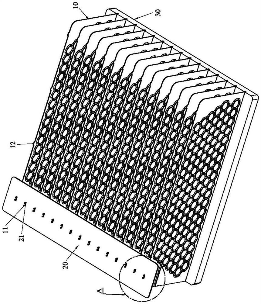
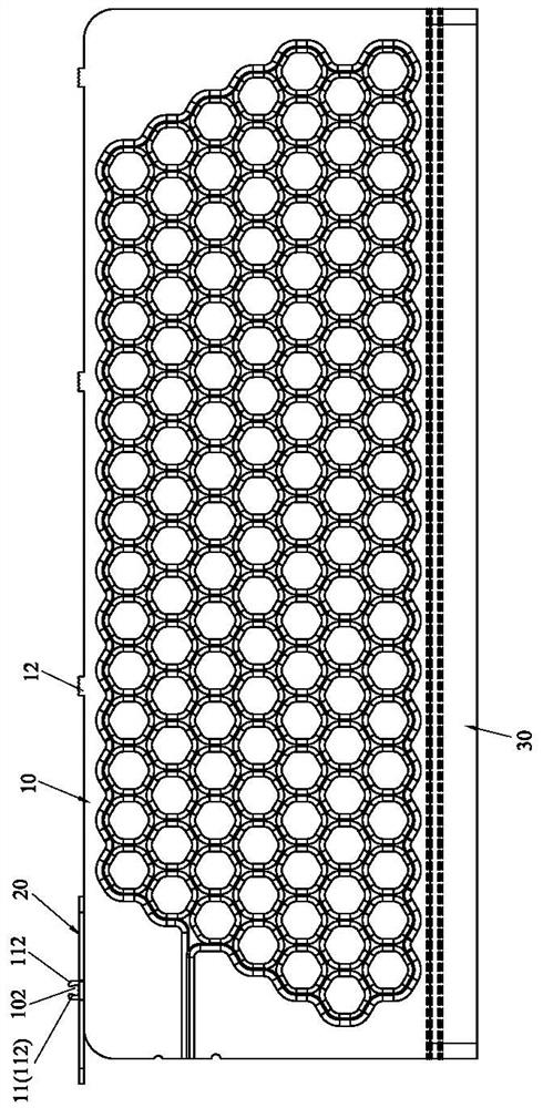
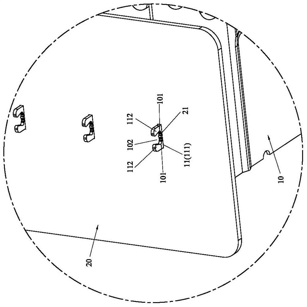
[0037] Please refer to Figure 1 to Figure 9 As shown, it shows the specific structure of the first preferred embodiment of the present invention, including a plurality of thin heat dissipation fins 10 and a positioning plate 20 .

[0038] The plurality of thin heat dissipation fins 10 are vertically arranged, and a positioning protrusion 11 extends from the top of each thin heat dissipation fin 10; a riveting protrusion 12 extends from the top of each thin heat dissipation fin 10, and the riveting protrusion 12 The protruding part 12 is used for riveted and fixed installation of a thin cover plate (not shown in the figure); in this embodiment, the thin heat dissipation fin 10 is an inflatable plate with good heat dissipation performance, and multiple thin heat dissipation fins The fins 10 are vertically arranged side by side at intervals and fixed on a heat dissipation base 30, and the positioning protrusions 11 are located on one side of the thin heat dissipation fins 10, an...


PUM


Abstract

The invention discloses a rapid positioning structure for riveting thin heat dissipation fins and thin cover plates, which includes a plurality of thin heat dissipation fins and a positioning plate; the plurality of thin heat dissipation fins are arranged vertically, and each thin heat dissipation fin There are positioning protrusions extending from the tops of the fins; the positioning plate is arranged on a plurality of thin heat dissipation fins, and a plurality of positioning holes are opened on the positioning plate, and the aforementioned positioning protrusions respectively pass through the positioning holes and extend upwards and align with the corresponding positioning holes. Cooperate with positioning. By providing a positioning plate, the positioning convex part is used to extend upward through the positioning hole and cooperate with the positioning hole for positioning, so that when the thin cover plate is installed, each riveting convex part and each riveting hole can be quickly aligned Installation saves time and effort, and during the riveting process, the positioning plate can effectively prevent the thin heat dissipation fins from swinging left and right, and the riveting convex part is not easy to come out of the riveting hole, thereby improving the quality of riveting installation and bringing more benefits to production. convenient.

Description

technical field [0001] The invention relates to the technology in the field of radiators, in particular to a rapid positioning structure for riveting thin heat dissipation fins and thin cover plates. Background technique [0002] The heat sink usually includes a heat dissipation base and heat dissipation fins arranged on the heat dissipation base. In order to improve the heat dissipation effect, the current heat sinks generally use thin heat dissipation fins. However, due to the weak strength of a single thin heat dissipation fin, it is easy to deform. , it is necessary to install thin cover plates on multiple thin heat dissipation fins to enhance the overall strength of the radiator. [0003] In order to improve the assembly efficiency of the thin cover plate, riveting is used in the prior art to fix the thin cover plate and multiple thin heat dissipation fins, such as the thin heat dissipation fin disclosed in the Chinese invention patent application (application number 20...

Claims


Application Information

Patent Timeline
Patent Type & Authority Patents(China)
IPC IPC(8): F28F9/26
CPCF28F9/268F28F2275/122
Inventor 黄崇贤
Owner DONG GUAN HAN XU HARDWARE & PLASTIC TECH CO LTD
Why Eureka
Try Eureka