

Electric power pulley
A technology of electric power and pulleys, applied in the direction of overhead lines/cable equipment, etc., can solve the problems of cumbersome operation, insufficient stability, loose screws, etc., and achieve the effect of simple operation and stable work
- Summary
- Abstract
- Description
- Claims
- Application Information
AI Technical Summary
Problems solved by technology
Method used
Image

Examples
Embodiment Construction
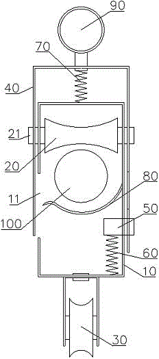
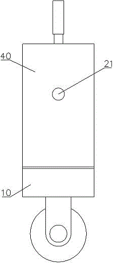
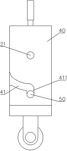
[0014] Examples, see Figure 1 to Figure 4 Shown: electric tackle, comprises frame 10. The inner upper side of the frame 10 is pivotally connected with an upper pulley 20 through a rotating shaft 21 , and the outer lower side is provided with a lower pulley 30 . An opening 11 for passing cables 100 is opened on the left side panel of the frame 10 . The outer card of the frame 10 is provided with a "U"-shaped baffle 40 . That is, the baffle plate 40 has a left side plate and a right side plate, and the upper end of the left side plate and the upper end of the right side plate are connected through the upper side plate. The left side of the baffle 40 is located on the left side of the left side of the frame 10 , and the left side of the baffle 40 matches the opening 11 . That is, the left side plate of the baffle plate 40 can open the opening 11 and close the opening 11 . The right side plate of the baffle plate 40 is located on the right side of the right side plate of the ...
PUM
 Abstract
Description
Claims
Application Information