Method for disassembling main shaft of vertical hydro-generator

A technology for hydroelectric generators and generators, which is applied in the manufacture of motor generators, electromechanical devices, electrical components, etc., which can solve the problems of difficult penetration of coupling bolts, difficult installation, and high risks, so as to shorten the maintenance period and reduce The risk of collision, the effect of reducing construction difficulty and risk

Active Publication Date: 2020-07-14
HUNAN WULING POWER ENG
View PDF5 Cites 2 Cited by
  • Summary
  • Abstract
  • Description
  • Claims
  • Application Information

AI Technical Summary

Problems solved by technology

In the process of adopting this method of construction, due to the deviation of the levelness of the foundation ring plane, the levelness and the center of the runner will deviate after being lowered, which directly leads to the following consequences: (1) due to the gap between the runner and the top cover and bottom ring. The façade gap is small, and it is easy to collide with each other and be damaged; (2) when the top cover is reinstalled, it is easy to collide with the runner, and it needs to be adjusted for a long time. The installation is difficult and the risk is high; (3) due to the The shaft bolts fit tightly with the bolt holes on the flange, and it is difficult for the coupling bolts to penetrate when the rotor is reassembled

Method used


Image

  • Method for disassembling main shaft of vertical hydro-generator
  • Method for disassembling main shaft of vertical hydro-generator
  • Method for disassembling main shaft of vertical hydro-generator

Examples


Embodiment 1

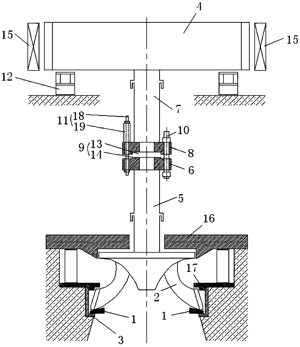
[0034] Such as figure 1 and figure 2 As shown, the large shaft dismounting method of the vertical hydroelectric generator of the present embodiment includes the following steps:

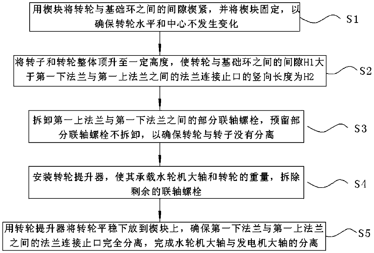
[0035] S1. Use the wedge 1 to wedge the gap between the runner 2 and the base ring 3, and fix the wedge 1 to ensure that the level and center of the runner 2 do not change;

[0036] S2. Use the rotor jacking device to lift the rotor 4 and the runner 2 to a certain height. At this time, the gap between the runner 2 and the base ring 3 is H1. There is a flange connection spigot 9 between the first upper flange 8 of the main shaft 7, and the vertical length of the flange connection 9 is H2, which satisfies H1>H2 (not shown in the figure of H1 and H2), that is The gap between the runner 2 and the base ring 3 is greater than the separation gap of the flange joint 9;

[0037] S3. Disassemble part of the coupling bolts 10 between the first upper flange 8 and the first lower flange 6, and reserve part of...

Embodiment 2

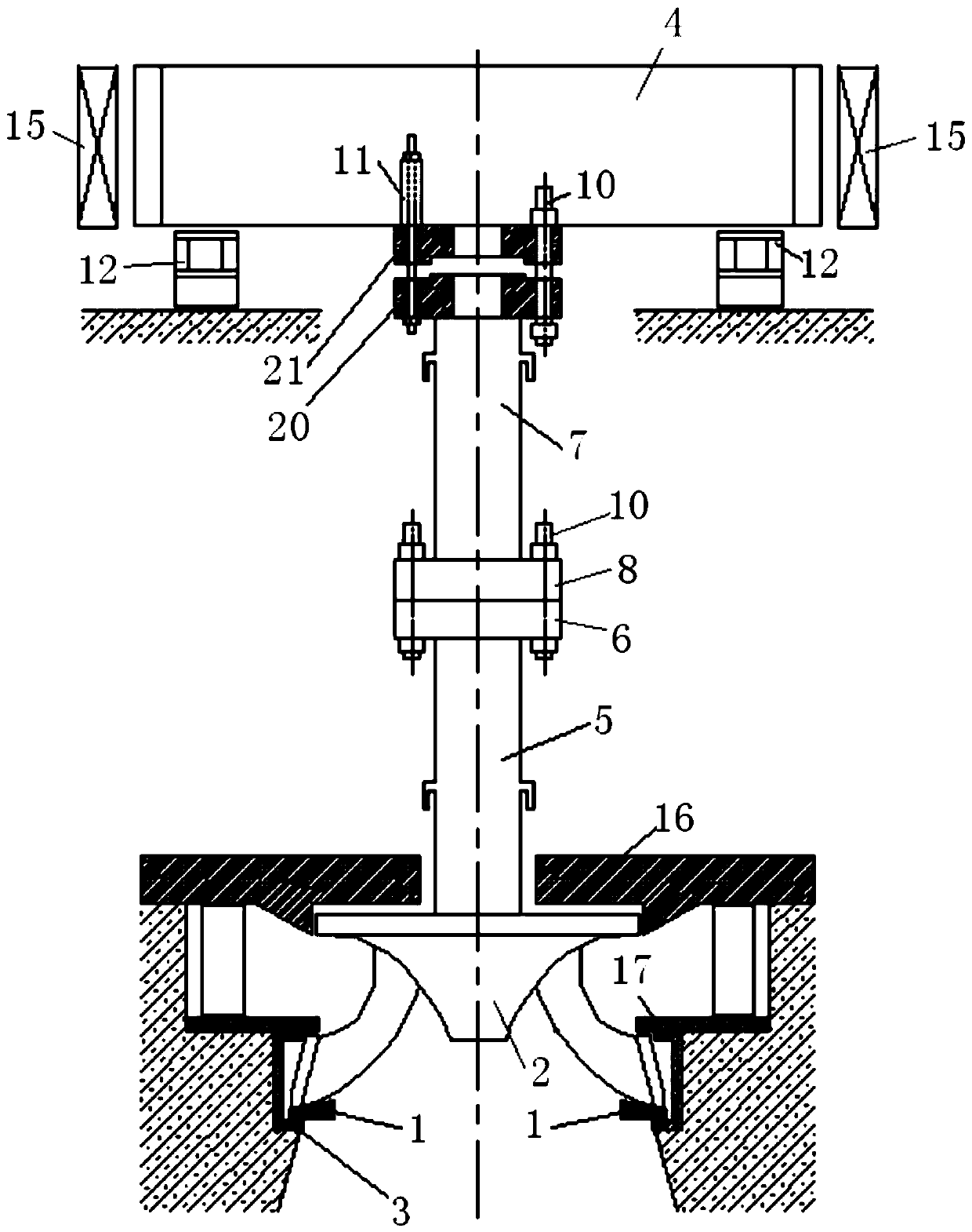
[0048] Such as image 3 As shown, the dismantling method of the large shaft of the vertical hydroelectric generator of this embodiment is the same principle as that of the embodiment 1, the only difference is that the embodiment 1 is aimed at the difference between the large shaft 7 of the generator and the large shaft 5 of the water turbine. The first upper flange 8 and the first lower flange 6 between the rotor 4 and the first lower flange 6 are disassembled. In this embodiment, the second upper flange 21 and the second lower flange 20 between the rotor 4 and the generator shaft 7 are disassembled. Specific steps are as follows:

[0049] S1. Use the wedge 1 to wedge the gap between the runner 2 and the base ring 3, and fix the wedge 1 to ensure that the level and center of the runner 2 do not change;

[0050] S2. Use the rotor lifting device to lift the rotor 4 and the runner 2 to a certain height. At this time, the gap between the runner 2 and the base ring 3 is H1, and th...


PUM


Abstract

The invention discloses a method for disassembling the main shaft of a vertical hydro-generator. The method comprises the following steps of: wedging a gap between a rotating wheel and a foundation ring by using a wedge block; integrally jacking a rotor and the rotating wheel to a certain height to enable the gap between the rotating wheel and the foundation ring to be greater than a flange connection seam allowance separation gap between a first lower flange and a first upper flange; disassembling a part of coupling bolts between the first upper flange and the first lower flange; installing arotating wheel lifter to make the rotating wheel lifter bear the weight of the rotating wheel; disassembling the rest coupling bolts; and stably lowering the rotating wheel onto the wedge block and ensuring that the flange connecting seam allowance between the first lower flange and the first upper flange is completely separated; and completing the separation of a water turbine main shaft from agenerator main shaft. According to the disassembling method, the wedge block is adopted to position the rotating wheel firstly, the original horizontal state of the rotating wheel is kept; the levelness and center of the rotating wheel are prevented from deviating severely; and therefore, the difficulty in a whole construction process is reduced.

Description

technical field [0001] The invention relates to a vertical hydraulic generator, in particular to a method for disassembling a large shaft of a vertical hydraulic generator. Background technique [0002] When the vertical hydro-generator is overhauled, the runner is placed on the base ring to separate the hydro-generator coupling (when the runner is at the operating height after the unit stops, the runner and the base ring are in the vertical direction With a certain clearance, the runner is hoisted and its bottom is horizontal). The main steps of disassembly are as follows: (1) Remove the coupling bolts (reserve 4); (2) Install the runner lifter to make it bear the weight of the runner, and then remove the remaining 4 bolts; (3) Use the runner lifter Lower the runner onto the base ring to separate the large shaft flange. In the process of adopting this method of construction, due to the deviation of the levelness of the foundation ring plane, the levelness and the center o...

Claims


Application Information

Patent Timeline
Patent Type & Authority Applications(China)
IPC IPC(8): H02K15/00B23P19/00
CPCB23P19/00H02K15/0006
Inventor 李明黄波
Owner HUNAN WULING POWER ENG
Why Eureka
Try Eureka