Independent double-magnet rocker type micro power generation device and wireless switch with power generation device
A power generation device and rocker technology, which is applied to electromechanical devices, electrical components, etc., can solve the problems of low power generation efficiency of self-generating devices, complicated magnetic circuits of self-generating devices, unstable control of household appliances, etc., and achieves simple and fast parts manufacturing. The effect of simple closed magnetic circuit and low manufacturing cost
- Summary
- Abstract
- Description
- Claims
- Application Information
AI Technical Summary
Problems solved by technology
Method used
Image
Examples
Embodiment 1
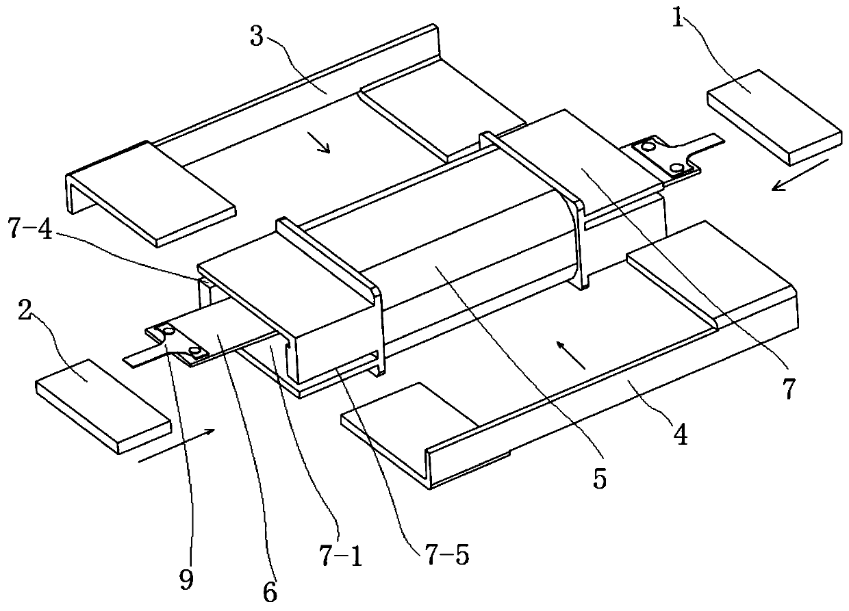
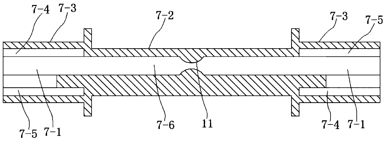
[0035] combine figure 2 , a kind of independent dual-magnet seesaw type miniature power generation device of the present embodiment comprises a coil assembly and a permanent magnet assembly, and the permanent magnet assembly includes a first soft magnetic frame 1, a second soft magnetic frame 2, a first permanent magnet 3 and a second Permanent magnet 4, the first soft magnetic frame 1 and the second soft magnetic frame 2 are U-shaped structures (see Figure 7 shown), both include the middle horizontal vertical board A-1 and two longitudinal horizontal boards A-2, the two longitudinal horizontal boards A-2 are respectively located on the left and right sides of the middle horizontal vertical board A-1, and the two longitudinal horizontal boards A-2 is arranged up and down; the two longitudinal horizontal plates A-2 are connected into an integrated structure through the middle horizontal vertical plate A-1; the first soft magnetic frame 1 and the second soft magnetic frame 2 are...
Embodiment 2
[0041] combine Figure 5 and Figure 6 , the basic structure of a kind of independent dual-magnet seesaw micro-generating device of the present embodiment is the same as that of Embodiment 1, the difference is that the first permanent magnet 3 and the second permanent magnet 4 are arranged on the same side, and the first permanent magnet 3 and the second permanent magnet The magnetic pole direction of the second permanent magnet 4 is identically arranged; One end of the soft magnetic plate 6 is positioned between the first permanent magnet 3 and the second permanent magnet 4, and the other end of the soft magnetic plate 6 is from the longitudinal horizontal plate of the first soft magnetic frame 1 Pass between A-2 and the longitudinal horizontal plate A-2 of the second soft magnetic frame 2; when the coil assembly, the permanent magnet assembly and the coil holder 7 are assembled in the present embodiment (see Figure 4 shown), the first permanent magnet 3 and the second perm...
PUM
 Abstract
Description
Claims
Application Information
 - R&D
- Intellectual Property
- Life Sciences
- Materials
- Tech Scout
- Unparalleled Data Quality
- Higher Quality Content
- 60% Fewer Hallucinations
Browse by: Latest US Patents, China's latest patents, Technical Efficacy Thesaurus, Application Domain, Technology Topic, Popular Technical Reports.
© 2025 PatSnap. All rights reserved.Legal|Privacy policy|Modern Slavery Act Transparency Statement|Sitemap|About US| Contact US: help@patsnap.com


