Magnetically Powered Reciprocating Engine And Electromagnet Control System

a reciprocating engine, electromagnet technology, applied in the direction of dynamo-electric converter control, motor/generator/converter stopper, multiple dynamo-motor starters, etc., can solve the problems of increasing the cost of fuel consumption, generating heat, noise, vibration and toxic by-products, etc., to achieve the maximum torque produced by the engine

Active Publication Date: 2012-10-18
MAGNETIC MILES LLC
View PDF1 Cites 2 Cited by
  • Summary
  • Abstract
  • Description
  • Claims
  • Application Information

AI Technical Summary

Benefits of technology

[0012]In general, an internal combustion reciprocating type engine is utilized by removing the cylinder heads and replacing them with electromagnetic coils. The piston(s) are modified to retain at least one and more, preferably a plurality, of permanent magnets. The standard timing system is also removed and is replaced with a fiber optic system which communicates with a high voltage DC switching mechanism for controlling the flow of power to the electromagnets in a manner that isolates the timing system from the magnetic impulses generated by the engine. In a preferred embodiment, power is supplied to the electromagnets via a series of electrical pulses that vary in duration to minimize power consumption and maximize the magnetic flux developed by the electromagnets. The power pulses facilitate delivery of different electrical pulses, thus magnetic flux, based on crankshaft angle to maximize torque delivery provided by the engine. The cooling system, if present, can also be removed, as well as the fuel delivery system.
[0019]It is still yet a further objective of the present invention to provide an electromagnet control system that provides variably pulsed electrical power to electromagnets based on crankshaft angle to maximize torque produced by the engine.

Problems solved by technology

However, reciprocating internal combustion engines suffer from disadvantages, many of which would no longer be acceptable if there were an alternative to the use of these engines.
They require fossil fuel, and suffer from many inefficiencies that cause them to generate heat, noise, vibration and toxic by-products; all of which we tolerate only because we have no economically suitable alternatives.
For example, some of the energy wasting features of internal combustion engines include friction, inefficient combustion, heat loss from the combustion chamber, aerodynamic drag of air moving through the engine, energy used by ancillary equipment like oil and water pumps, and imperfect valve timing.
Another issue that affects the efficiency of these engines is that they must be designed to reduce emissions requiring compromises in design.
This means that about 82% of the energy we put into our vehicles in the form of fossil fuels is wasted exiting the engine in the form of non-useful byproducts.
Various types of alternative fuels and engine configurations have been suggested, some with more success than others, but overall most have met with very limited success.
However, these fuels require agricultural land, tractors for planting and harvesting, and distilleries for converting the biomass into fuel.
Even if these fuels were developed on a scale suitable for use, there is no suitable system for distributing the fuel to the general public.
This causes several problems, such as arcing between the contacts, and results in pre-mature failure.
In addition, electromagnets operating at high current loads for extended periods of time generate a considerable amount of heat.
The increase in heat significantly reduces efficiency and often results in failure of the electromagnetic coil.
In addition, the magnetic fields generated by the electromagnets often cause problems such as cascading avalanche breakdown, induced EMF, spikes and voltage clips in other engine systems, such as the timing system.

Method used


Image

  • Magnetically Powered Reciprocating Engine And Electromagnet Control System
  • Magnetically Powered Reciprocating Engine And Electromagnet Control System
  • Magnetically Powered Reciprocating Engine And Electromagnet Control System

Examples


Embodiment Construction

[0034]While the present invention is susceptible of embodiment in various forms, there is shown in the drawings and will hereinafter be described a presently preferred, albeit not limiting, embodiment with the understanding that the present disclosure is to be considered an exemplification of the present invention and is not intended to limit the invention to the specific embodiments illustrated.

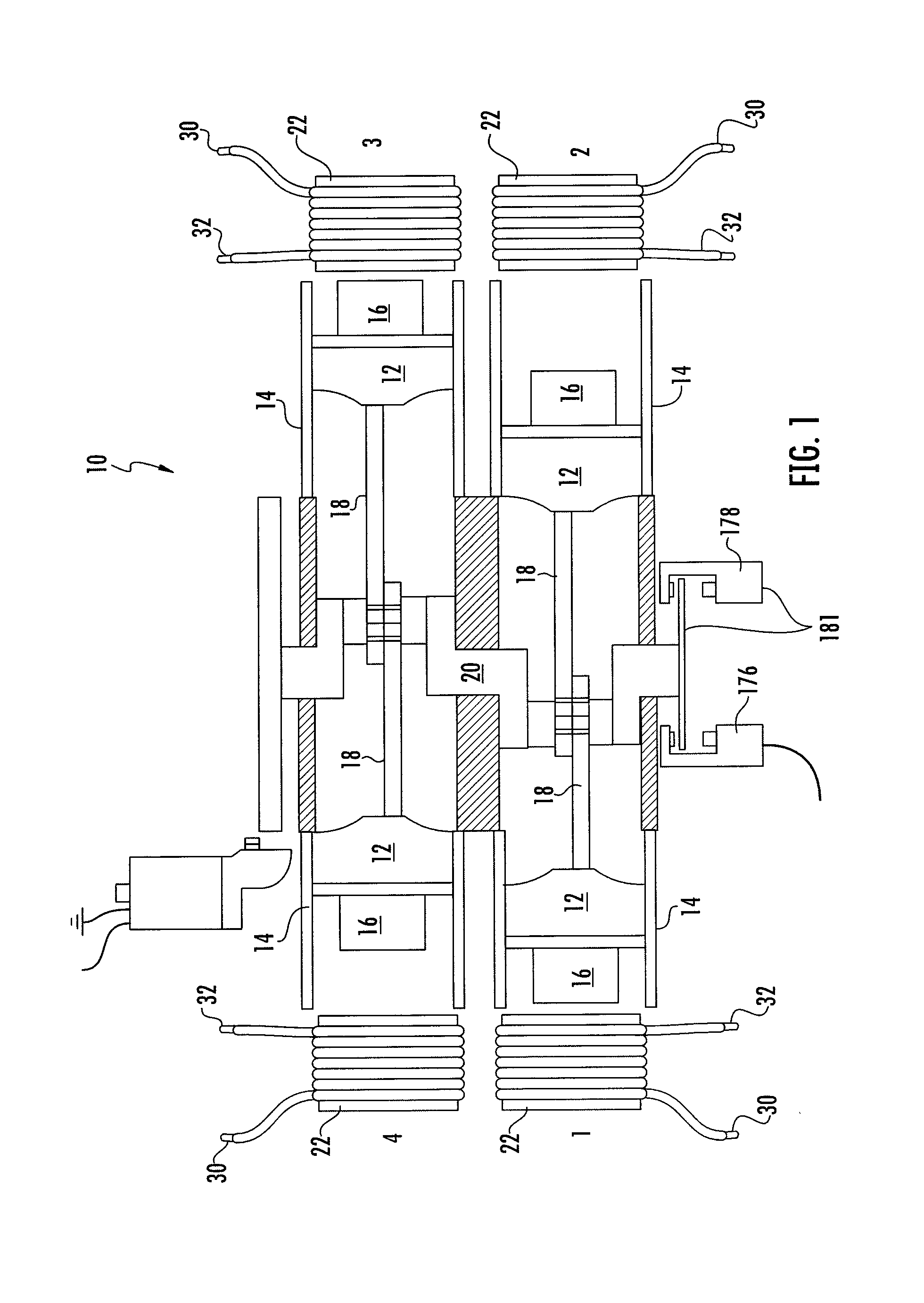
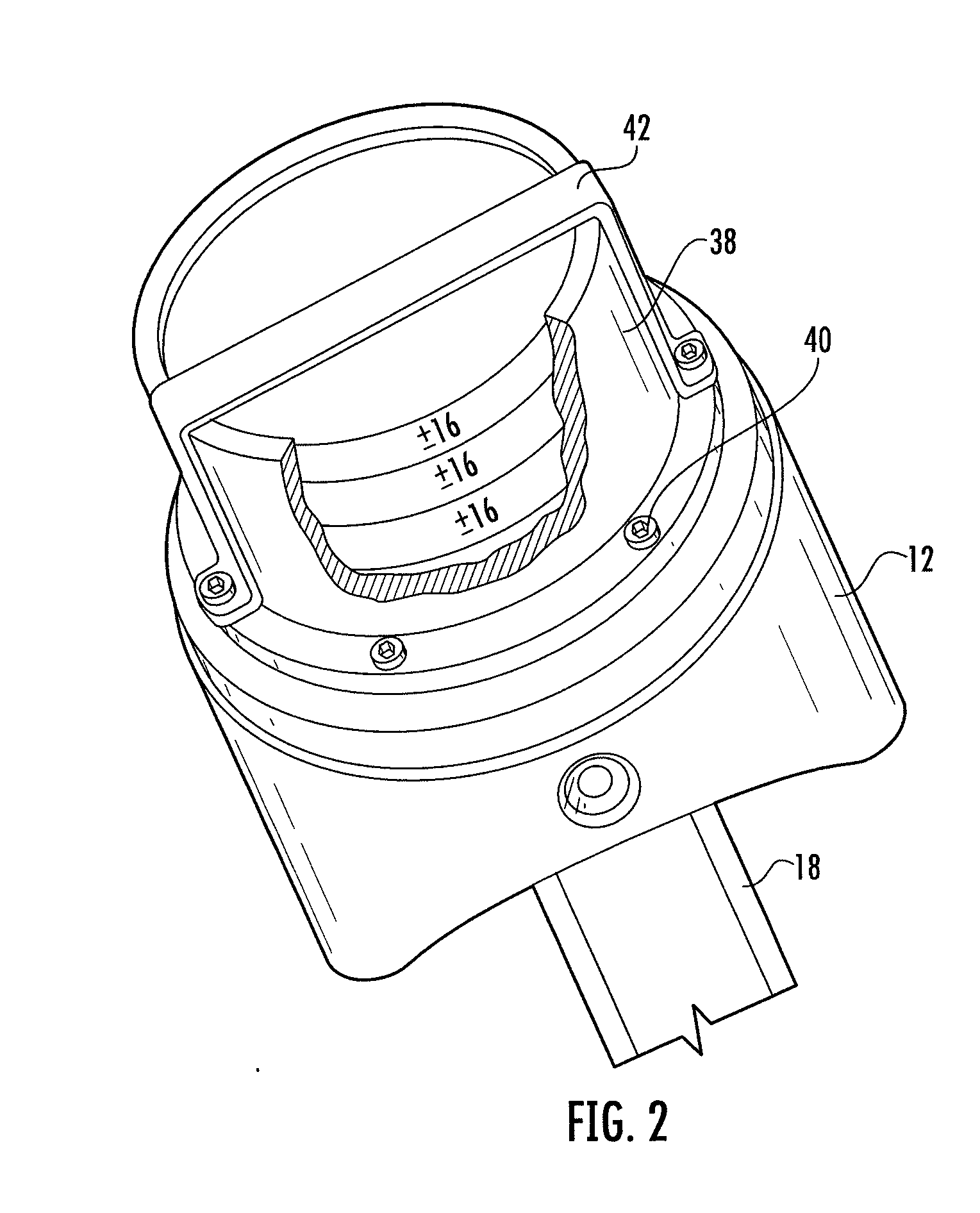
[0035]Referring to FIGS. 1 and 2, a magnetically operated reciprocating engine 10 is illustrated. The magnetically operated reciprocating engine 10 includes at least one piston 12 constructed and arranged to reciprocate along a substantially linear path illustrated herein as a cylinder 14. The piston 12 includes at least one, and preferably a plurality of permanent magnets 16 secured thereto. The magnets are preferably secured to a top surface of the piston 12 via a non-metallic sleeve 38. The sleeve may be secured to the top surface of the piston with fasteners 40, and a strap member 42 may...


PUM


Abstract

The instant invention provides a magnetically controlled reciprocating engine having a unique electromagnet control system. The engine is constructed and arranged to operate from a stored power source such as batteries to provide extended run times by controlling the power supplied to the electromagnets in a manner that controls heat generation within the electromagnetic coils, thereby increasing coil life. The control system is also capable of controlling engine speed and / or torque outputs to make the engine versatile for a wide variety of uses. The system is constructed and arranged to be utilized on new or pre-existing engines of various configurations and may be utilized in other industries or devices that benefit from the use of electromagnets.

Description

CROSS REFERENCE TO RELATED APPLICATIONS[0001]This application is a continuation of U.S. patent application Ser. No. 12 / 701,781, filed Feb. 8, 2010, entitled, “Magnetically Powered Reciprocating Engine And Electromagnet Control System”, the contents of which are incorporated herein in their entirety.FIELD OF THE INVENTION[0002]This invention relates generally to reciprocating engines. More specifically, the invention is a magnetically powered reciprocating engine and electromagnet control system adaptable for use wherever internal combustion engines are utilized.BACKGROUND OF THE INVENTION[0003]Reciprocating internal combustion engines, e.g. Otto and Diesel cycle engines are a major factor in just about every aspect of life here and abroad. Reciprocating internal combustion engines facilitate our way of life by providing us with transportation, consumer products, safety, medical assistance, and power generation to name only a few. However, reciprocating internal combustion engines su...

Claims


Application Information

Patent Timeline
Patent Type & Authority Applications(United States)
IPC IPC(8): H02K33/00H02K7/075
CPCH02K7/075H02K16/00H02K33/06H02K41/03H02K7/065H02K33/00H02K33/10H02P25/027H02P25/032
Inventor MILES, STEPHENCRISTOFORO, MICHAEL
Owner MAGNETIC MILES LLC
Why Eureka
Try Eureka