
Gas pressure regulator for regulating the pressure of a gaseous fuel, system for supplying an internal combustion engine with gaseous fuel using such a gas pressure regulator, and method for operating the system

A gas pressure, gaseous fuel technology, applied in the charging system, internal combustion piston engine, combustion engine and other directions, can solve the problems of time-consuming, expensive, reducing system efficiency, etc., to achieve the effect of function, reliable function and reliable sealing

Active Publication Date: 2022-05-24
ROBERT BOSCH GMBH
View PDF7 Cites 0 Cited by
  • Summary
  • Abstract
  • Description
  • Claims
  • Application Information

AI Technical Summary

Problems solved by technology

Sealing against one another with high pressure differences of several hundred bar is technically very complex and such gas pressure regulators are correspondingly expensive and reduce the efficiency of the entire system

Method used


Image

  • Gas pressure regulator for regulating the pressure of a gaseous fuel, system for supplying an internal combustion engine with gaseous fuel using such a gas pressure regulator, and method for operating the system
  • Gas pressure regulator for regulating the pressure of a gaseous fuel, system for supplying an internal combustion engine with gaseous fuel using such a gas pressure regulator, and method for operating the system
  • Gas pressure regulator for regulating the pressure of a gaseous fuel, system for supplying an internal combustion engine with gaseous fuel using such a gas pressure regulator, and method for operating the system

Examples


Embodiment Construction

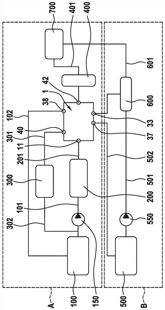
[0022] figure 1 A system of the invention for supplying a gaseous fuel to an internal combustion engine is shown. The system is designed to supply both gaseous fuel and liquid fuel to the injector, which can then introduce the two fuels simultaneously or with a time offset into the combustion chamber of the internal combustion engine. To this end, the system includes gas systems and liquid systems. exist figure 1The gas system denoted by A has a gas tank 100 in which gaseous fuel is preferably stored cryogenically and in which a low pressure exists. The gaseous fuel is compressed by the gas pump 150 and supplied via the line 101 to the intermediate tank 200 where the gaseous fuel is intermediately stored. The gaseous fuel is supplied via line 201 to the gas pressure regulator 1, which regulates the gas pressure to the desired level and finally to the gas rail 400, where the gaseous fuel is maintained by injection into the combustion chamber of the internal combustion engine...


PUM


Abstract

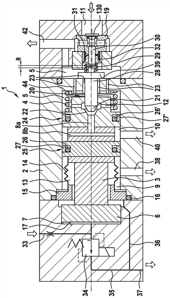
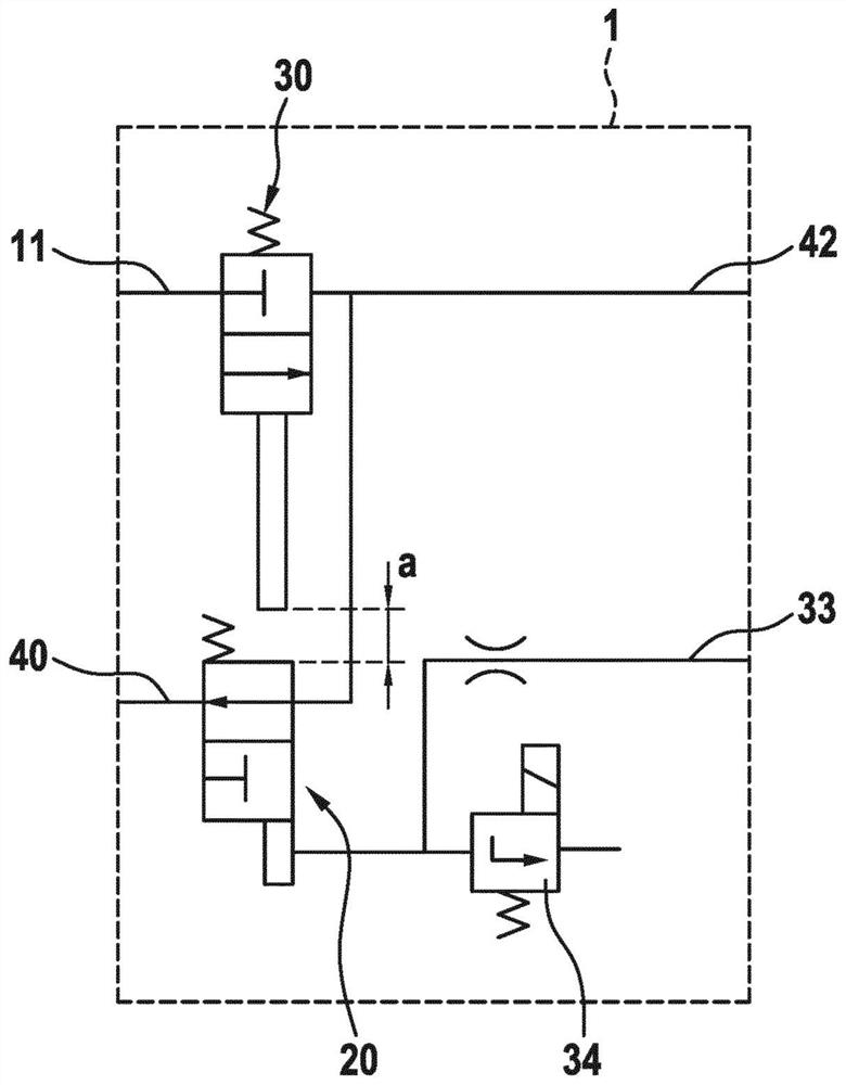
The invention relates to a gas pressure regulator (1) for regulating the pressure of a gaseous fuel, said gas pressure regulator having a housing (2) in which a gas piston (3) movable longitudinally is arranged ), the gas piston delimits a gas chamber (5) and delimits a pressure chamber (7) that can be filled with a working fluid, wherein the gas piston (3) has a first seal (24) surrounding its outer side, The gas piston (3) is guided sealingly on the housing (2) by means of the first seal and the first seal seals the gas chamber (5). The cooperation of the gas piston (3) and the valve seat (21) forms an overflow valve (20), via which gas can be led out of the gas chamber (5). A second circumferential seal (25) is formed on the outside of the gas piston (3), by means of which the gas piston (3) is likewise guided in a sealing manner in the housing (2) , wherein the gas piston (3) is at least partially surrounded by a low-pressure gas chamber (9), and the second seal (25) separates the low-pressure gas chamber (9) from the gas return chamber (10) , wherein the gas chamber (5) can be connected to the gas return chamber (10) through the overflow valve (20). The invention also relates to a system for supplying an internal combustion engine with gaseous fuel, the system having an intermediate tank (200) and such a gas pressure regulator (1). Furthermore, in a method for operating the system there is a return accumulator ( 300 ), the pressure of which is set between the pressure in the gas chamber ( 5 ) and the pressure in the gas tank ( 100 ).

Description

technical field [0001] The invention relates to a gas pressure regulator for regulating the pressure of a gaseous fuel, as the gas pressure regulator is used to supply a gaseous fuel at a predetermined pressure to an internal combustion engine. Furthermore, the device relates to a system for supplying a gaseous fuel to an internal combustion engine using such a gas pressure regulator and a method for operating the system. Background technique [0002] A gas pressure regulator for supplying an internal combustion engine with gaseous fuel at a certain pressure is known from the prior art, for example from DE 10 2016 207 743 A1. Such systems have a gas tank from which gaseous fuel is removed by means of a gas pump. The gas pump compresses gas and supplies it to the intermediate tank. A further gas accumulator, the so-called gas rail, is fed from the intermediate tank, in which the gaseous fuel is maintained at a predetermined pressure in order to be finally introduced into th...

Claims


Application Information

Patent Timeline
Patent Type & Authority Patents(China)
IPC IPC(8): F02D19/10F02D19/06F02M21/02F16K31/124
CPCF02M21/0293F02M21/0239F02M21/0245F02D19/023F02D19/0642F02D19/0678F02M21/0233Y02T10/30
Inventor A·谢尔D·瓦勒
Owner ROBERT BOSCH GMBH
Learn More