A method of manufacturing a camera bracket

A manufacturing method and camera technology, which are applied in the coating and other directions, can solve the problems of high surface treatment defect rate, no positioning structure, low efficiency, etc., and achieve the effects of high punching precision, improving production efficiency and reducing production costs.

Active Publication Date: 2022-05-31
深圳市高塑达电子有限公司
View PDF0 Cites 0 Cited by
  • Summary
  • Abstract
  • Description
  • Claims
  • Application Information

AI Technical Summary

Problems solved by technology

This manufacturing method has many defects: first, the inlaid steel sheets are manufactured in bulk, which is inefficient and easy to deform; second, the inlaid steel sheets have to be installed in the injection mold one by one, which is inefficient; third, there is no precision in the surface treatment of the bracket. positioning structure, the surface treatment defect rate is high

Method used


Image

  • A method of manufacturing a camera bracket

Examples


Embodiment Construction

[0017] The invention will be further described in detail below in conjunction with the accompanying drawings and specific embodiments.

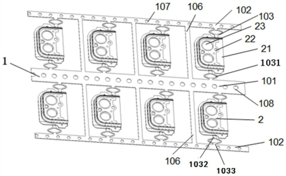
[0018] like figure 1 As shown, the manufacturing method of the camera bracket of the present embodiment includes the following steps: (1) manufacture the strip 1 containing the inlaid steel sheet 21 of the camera bracket 2 by stamping; (2) place the strip 1 Placed in the injection mold, the insulating plastic body of the camera bracket 2 and the inlaid steel sheet 21 are injection molded into one body by injection molding.

[0019] In the method for manufacturing the camera bracket of the present invention, the material strip 1 containing the inlaid steel sheet 21 is produced by stamping first, and then the material strip 1 is placed in an injection mold for injection molding, so that continuous batch production of injection molding can be realized, and the production process is simplified. , Improve production efficiency and reduce producti...


PUM


Abstract

The invention relates to a method for manufacturing a camera bracket, comprising the following steps: step 1, manufacturing a material strip containing a camera bracket inlaid with steel sheets by stamping; step 2, placing the material strip in an injection mold, The insulating plastic body of the camera bracket and the inlaid steel sheet are injection molded into one body by injection molding. Through the manufacturing method of the camera bracket of the present invention, the production efficiency can be improved and the production cost can be reduced.

Description

technical field [0001] The invention relates to a method for manufacturing electronic accessories, in particular to a method for manufacturing a camera bracket. Background technique [0002] The manufacturing method of the existing camera bracket is generally as follows: the mosaic bracket of the camera bracket is manufactured first, and the mosaic bracket is made of metal material. Each mounting bracket is a separate part. Then install the inlay brackets into the injection mold one by one, and fix them in the injection mold through the process holes on the inlay brackets. Then, the insulating plastic body of the camera bracket and the mosaic bracket are injection molded into one body by injection molding. This manufacturing method has many defects: first, the inlaid steel sheets are manufactured in bulk, which is inefficient and easy to deform; second, the inlaid steel sheets have to be installed in the injection mold one by one, which is inefficient; third, there is no p...

Claims


Application Information

Patent Timeline
Patent Type & Authority Patents(China)
IPC IPC(8): B29C45/14
CPCB29C45/14B29C45/1418B29C2045/14237
Inventor 龙际恩
Owner 深圳市高塑达电子有限公司
Why Eureka
Try Eureka