Sinker mounting structure with large-stroke swing effect for computerized flat knitting machine

A computerized flat knitting machine and installation structure technology, applied in textiles and papermaking, weft knitting, knitting, etc., can solve problems such as sinker function failure, shedding, and yarn floating in woven clothes

Active Publication Date: 2020-07-17
常熟创富针织机械有限公司
View PDF8 Cites 0 Cited by
  • Summary
  • Abstract
  • Description
  • Claims
  • Application Information

AI Technical Summary

Problems solved by technology

However, the swing range of the sinker is limited, the yarn of the knitted clothes may still float up, and the pressing effect is not in place
[0004] In order to solve this technical problem, a utility model patent with the authorized notification number CN205501560U discloses a sinker for a computerized flat knitting machine, which includes a sinker body hinged on the insertion piece of the needle bed and a spring fixed at the bottom of the sinker body to set the sinker. There is a tongue on the lower side of the pressing part of the chip body, and the sinker can swing in a wide range to reduce the yarn floating; however, this structural scheme needs to rely on springs to achieve high-precision installation and hinge transition, and the installation requirements are relatively high, and the spring Easy to occur or fall off, causing the function of the sinker to fail

Method used


Image

  • Sinker mounting structure with large-stroke swing effect for computerized flat knitting machine
  • Sinker mounting structure with large-stroke swing effect for computerized flat knitting machine
  • Sinker mounting structure with large-stroke swing effect for computerized flat knitting machine

Examples


Embodiment 1

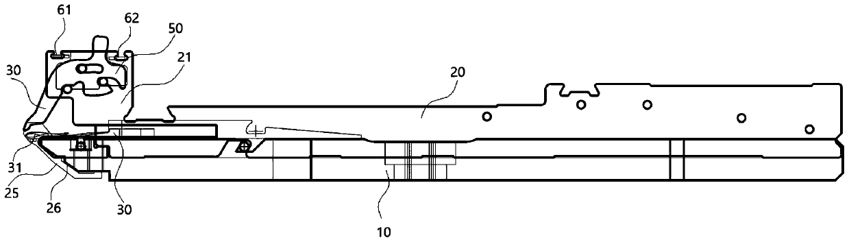
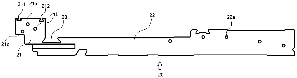
[0068] Example 1: see figure 1As shown, a needle plate insert installation structure of a computerized flat knitting machine includes inserts 20 that are fixed and installed on the needle plate 10 of a computerized flat knitting machine in parallel, and each adjacent insert 20 is formed for installing knitting needles. 30 needle slot, see further figure 2 As shown, the insert 20 adopts an integral molding, and the front end of the insert adopts the insert hinge mounting block 21. Preferably, in this embodiment, the insert 20 includes an insert body 22 integrally connected with the insert hinge mounting block 21. The insert body 22 is provided with a plurality of mounting holes 22a for fixed installation and connection with the needle plate 10, and a needle ruler ( figure 1 Not shown) the needle gauge limit groove 23; specifically preferably, in this embodiment, the outer diameter of the needle shank of the knitting needle 30 is in the range of 0.8-1.5mm;

[0069] In this em...

Embodiment 2

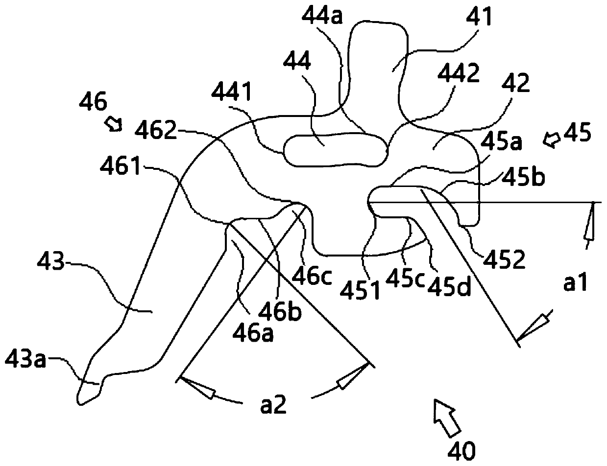
[0079] Example 2: see Figure 7 and Figure 8 As shown, a sinker installation structure with a large-stroke swing effect for a computerized flat knitting machine. The sinker 100 adopts an integrally formed structure, including a Sink triangle assembly located at the upper end and used for connecting with the computerized flat knitting machine head (not shown in the figure). ) drives the cooperating piece bell 110, the subsidence hinged mounting part 120 and the thread-pressing swing arm 130 matched with the knitting needle 200, and the sinking hinged mounting part 120 connects the piece-picking bell 110 and the thread-pressing swing arm 130 as one; specifically preferably , in this embodiment, the outer diameter range of the needle bar of the knitting needle 210 is 5-9mm; Cooperate with the needle tongue 211 of the knitting needle 210 to be used for the tooth mouth piece 230 for stripping, and the thread pressing tongue 211 performs a large-stroke swing relative to the tooth ...


PUM

PropertyMeasurementUnit
Lengthaaaaaaaaaa
Outer diameteraaaaaaaaaa

Abstract

The invention discloses a sinker mounting structure with a large-stroke swing effect for a computerized flat knitting machine. A settlement hinge mounting part is provided with a closed upper slidingkidney slot and a closed corner chute; a first hinge hole and a second hinge hole which are matched with the closed upper sliding kidney slot and the closed type corner chute in a limiting and slidinghinge manner are respectively arranged on the front end of an insertion piece, a sliding hinge structure with the large-stroke swing effect is formed, the front end of the insertion piece and a sinker are hinged and matched through a spacer, and the sinker is arranged between the front end of the insertion piece and the spacer. According to the sinker mounting structure, a reliable and stable large-stroke motion track is ensured on the basis of realizing the large-stroke swing effect, so that a reliable line pressing effect is achieved; and meanwhile, the sinker with the large-stroke swing effect adopts an integral forming piece, and is simple in structure, stable in installation, free of loosening or accidental movement, convenient and efficient in machining, assembly and disassembly processes, and suitable for large-scale popularization and application.

Description

technical field [0001] The invention belongs to the field of computerized flat knitting machine manufacturing, and in particular relates to a sinker installation structure for a computerized flat knitting machine with a large-stroke swing effect. Background technique [0002] As we all know, the base plate of the needle bed of the motor flat machine is used to install the needle board. The needle board mainly includes the needle board insert used for installing the knitting needles, and the sinker connected with the needle board insert. At the same time, the sinker is installed on the machine head. The Xinke triangular assembly drives the connection and cooperates. During the knitting process of the machine head, it mainly realizes the suppression effect on the yarn and avoids the yarn from floating. [0003] Please refer to the utility model patent with the notification number CN201343618Y, which discloses a sinker for computerized flat knitting machines, which uses a hamme...

Claims


Application Information

Patent Timeline
IPC IPC(8): D04B15/10D04B15/06
CPCD04B15/06D04B15/10
Inventor 李鹏傅拥军
Owner 常熟创富针织机械有限公司
Why Eureka
Try Eureka