Scroll compressor and thrust plate for same

A scroll compressor and thrust plate technology, applied in the field of scroll compressors and thrust plates, can solve the problems of wear on the thrust surface, insufficient lubrication, complex structure, etc., and achieve the effect of avoiding wear and enhancing lubrication

Pending Publication Date: 2020-07-17
EMERSON CLIMATE TECH (SUZHOU) CO LTD
View PDF0 Cites 0 Cited by
  • Summary
  • Abstract
  • Description
  • Claims
  • Application Information

AI Technical Summary

Problems solved by technology

At present, most of the lubricating structures used between the end plate of the orbiting scroll part and the thrust surfac

Method used


Image

  • Scroll compressor and thrust plate for same
  • Scroll compressor and thrust plate for same
  • Scroll compressor and thrust plate for same

Examples


Example Embodiment

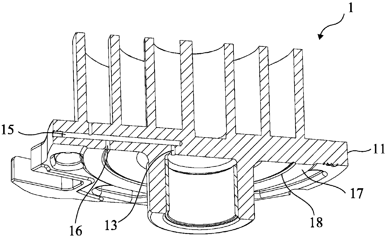
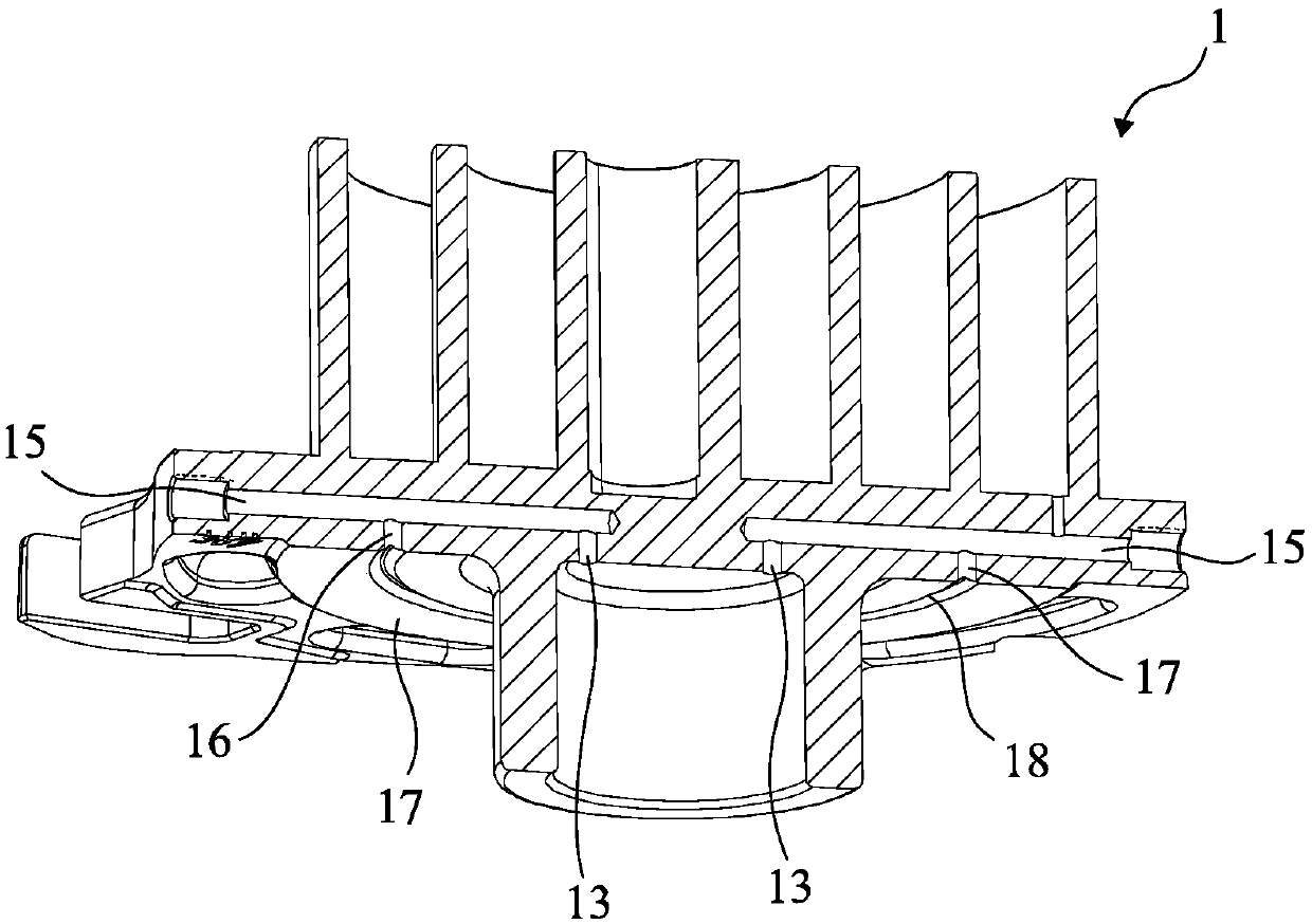
[0032] figure 1 A first comparative example with respect to the embodiment of the present invention is shown. figure 1 The first comparative example shown discloses a movable scroll component 1 for a scroll compressor. The movable scroll component 1 includes an end plate 11 on which an oil inlet 13 and a transverse hole 15 are provided. , The oil outlet 16 and an annular oil groove 18 are provided on the thrust surface 17 of the movable scroll component 1. The lubricating oil enters from the oil inlet 13 and flows along the horizontal hole 15, and then flows from the oil outlet 16 to the annular oil groove 18, and finally overflows from the annular oil groove 18 to lubricate the stop of the end plate 11 of the movable scroll component 1. The thrust surface 17 and the thrust surface (not shown) of the thrust plate supporting the thrust surface 17 of the end plate 11 when the scroll compressor is operated.

[0033] In the first comparative example, since the annular oil groove is p...


PUM


Abstract

The invention discloses a thrust plate (100) for a scroll compressor (10) and the scroll compressor (10) comprising the thrust plate. The thrust plate (100) comprises a thrust surface (110) located ona first face of the thrust plate (100), an annular oil groove (102) located in a second face (130), opposite to the first face, of the thrust plate (100), and a plurality of oil supply through holes(104) extending from the bottom of the annular oil groove (102) to penetrate through the thrust plate (100) and reach the thrust surface (110). The thrust plate can supply oil more efficiently withoutdamaging the thrust surface.

Description

technical field [0001] The present invention relates to a thrust plate for a scroll compressor and a scroll compressor including the thrust plate. Background technique [0002] In a scroll compressor, the compression of fluid is achieved through the relative motion between the orbiting scroll member and the fixed scroll member. In order to provide axial support for the movable scroll part, a thrust plate is arranged on one side of the end plate of the movable scroll part. The contact surface (thrust surface) between the end plate of the movable scroll member and the thrust plate needs to be sufficiently lubricated to reduce friction and wear between the two. At present, most of the lubricating structures used between the end plate of the orbiting scroll part and the thrust surface of the thrust plate have the defects of complex structure, insufficient lubrication or serious wear of the thrust surface. [0003] Therefore, the inventors of the present invention believe that ...

Claims


Application Information

Patent Timeline
IPC IPC(8): F04C29/00F04C29/02F04C18/02
CPCF04C18/0215F04C29/00F04C29/02
Inventor 张跃缪仲威范忆文
Owner EMERSON CLIMATE TECH (SUZHOU) CO LTD
Why Eureka
Try Eureka