Disparity map cavity filling method and device, electronic equipment and storage medium

A filling method and filling device technology, which are applied in the field of image processing, can solve the problems of stripe defects, highlight spots, and time-consuming filling of disparity map holes, and achieve the effect of avoiding stripe defects and highlight spots and short time-consuming effects.

Active Publication Date: 2020-07-17
MEGVII BEIJINGTECH CO LTD
View PDF9 Cites 1 Cited by
  • Summary
  • Abstract
  • Description
  • Claims
  • Application Information

AI Technical Summary

Problems solved by technology

The scan line filling algorithm directly selects the minimum value of the effective parallax value on the left and the effective parallax value on the right for the pixels to be filled in the area to be filled, resulting in obvious stripe defects
The variable-size average filtering algorithm is to iteratively filter the area to be filled through the average filter window from large to small to determine the disparity value of each pixel to be filled. On the one hand, for each pixel to be filled, it needs to go through The disparity value of the pixel to be filled can only be determined after multiple iterations of filtering, resulting in a long time-consuming disparity map hole filling
On the other hand, bright spots appear at pixels with wrong disparity values ​​determined

Method used


Image

  • Disparity map cavity filling method and device, electronic equipment and storage medium
  • Disparity map cavity filling method and device, electronic equipment and storage medium
  • Disparity map cavity filling method and device, electronic equipment and storage medium

Examples


Embodiment Construction

[0020] The application will be further described in detail below in conjunction with the accompanying drawings and embodiments. It should be understood that the specific embodiments described here are only used to explain related inventions, rather than to limit the invention. It should also be noted that, for the convenience of description, only the parts related to the related invention are shown in the drawings.

[0021] It should be noted that, in the case of no conflict, the embodiments in the present application and the features in the embodiments can be combined with each other. The present application will be described in detail below with reference to the accompanying drawings and embodiments.

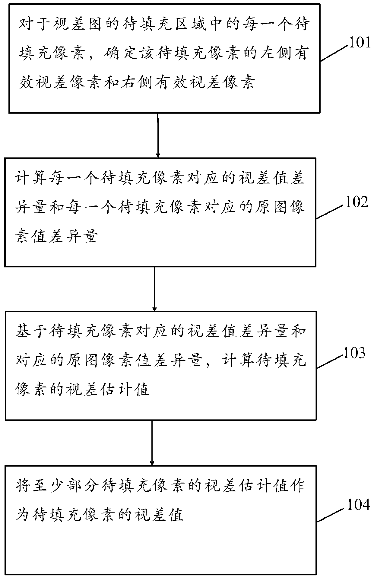
[0022] figure 1 A flow chart of a method for filling holes in a disparity map provided by an embodiment of the present application is shown, and the method includes:

[0023] Step 101, for each pixel to be filled in the area to be filled in the disparity map, determine the ...


PUM


Abstract

The embodiment of the invention provides a disparity map cavity filling method and device, and the method comprises the steps: determining a left effective disparity pixel of a to-be-filled pixel anda right effective disparity pixel of the to-be-filled pixel for each to-be-filled pixel; calculating a parallax difference value corresponding to a to-be-filled pixel and an original image pixel valuedifference value corresponding to the to-be-filled pixel, and calculating a parallax estimation value of the to-be-filled pixel based on the parallax difference value corresponding to the to-be-filled pixel and the original image pixel value difference value corresponding to the to-be-filled pixel; and taking the parallax estimation values of at least part of the to-be-filled pixels as parallax values of the to-be-filled pixels. Meanwhile, the relevance between the parallax value difference of the effective parallax pixels on the two sides of the to-be-filled pixel and the parallax value of the to-be-filled pixel and the relevance between the pixel value difference of the original image pixels corresponding to the effective parallax pixels on the two sides and the parallax value of the to-be-filled pixel are considered. Stripe flaws and highlight spots are avoided, and parallax image hole filling is completed in a short time.

Description

technical field [0001] The present application relates to the field of image processing, in particular to a method and device for filling holes in a disparity map, and a storage medium for electronic equipment. Background technique [0002] A disparity map is an image used to represent the translation relationship between a target image and a reference image in stereo matching technology. The steps of consistency detection, occlusion detection, and mismatch detection in stereo matching technology all rely on the disparity map. Since the reference image does not contain all the required information in the target image, resulting in holes in the target image, the disparity map includes regions to be filled corresponding to the holes in the target image. Before the step of relying on the disparity map in the stereo matching technology using the disparity map, it is necessary to fill the disparity map hole in the area to be filled in the disparity map, that is, for each pixel t...

Claims


Application Information

Patent Timeline
Patent Type & Authority Applications(China)
IPC IPC(8): H04N13/122
CPCH04N13/122
Inventor 王鹏
Owner MEGVII BEIJINGTECH CO LTD
Why Eureka
Try Eureka