Electric fluid flow heater with heating element support member

A technology for electric heaters and fluid heating, which is applied in the direction of fluid heaters, heating element shapes, water heaters, etc., and can solve problems such as damage to heating elements

Active Publication Date: 2020-07-24
康泰尔有限公司
View PDF4 Cites 0 Cited by
  • Summary
  • Abstract
  • Description
  • Claims
  • Application Information

AI Technical Summary

Problems solved by technology

[0005] Although conventional electric heaters may be able to achieve high temperatures on the order of 1100°C, the high gas velocity and large pressure differential cause vibration and movement of the heating element (and the surrounding tube (heating block)), so that the heating element is still subjected to Mechanical shocks and stresses that inevitably lead to breakage

Method used


Image

  • Electric fluid flow heater with heating element support member
  • Electric fluid flow heater with heating element support member
  • Electric fluid flow heater with heating element support member

Examples


Embodiment Construction

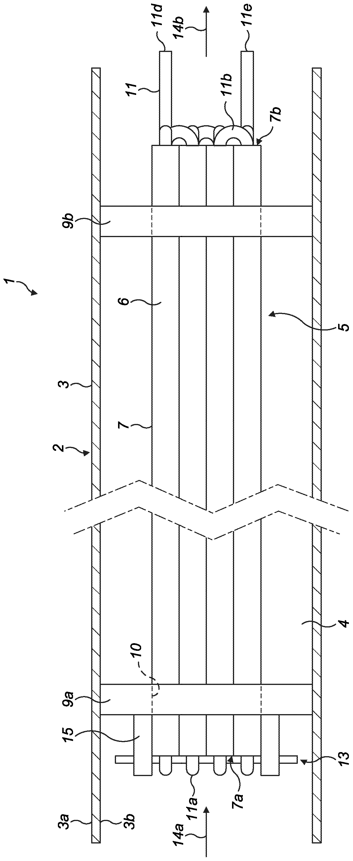
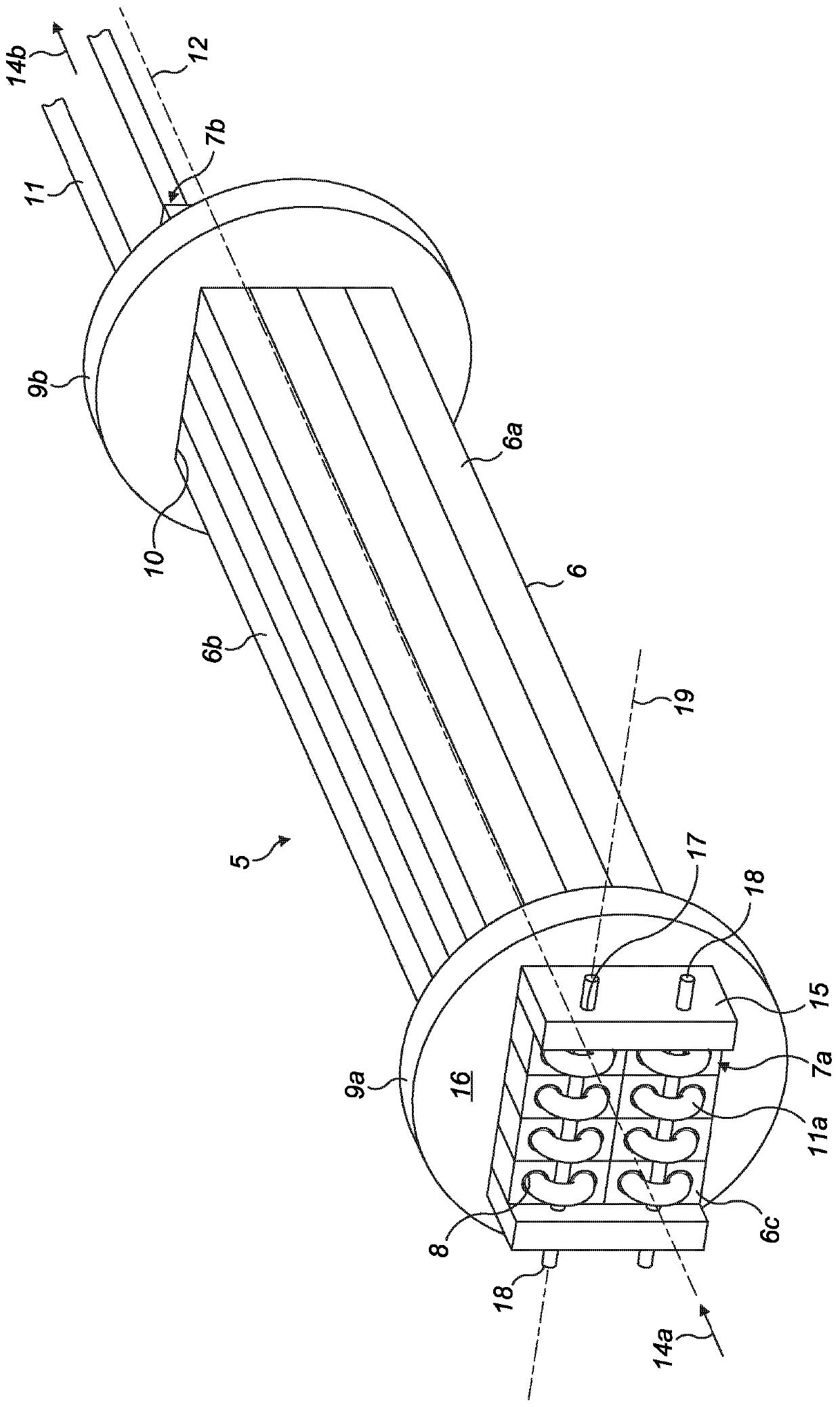
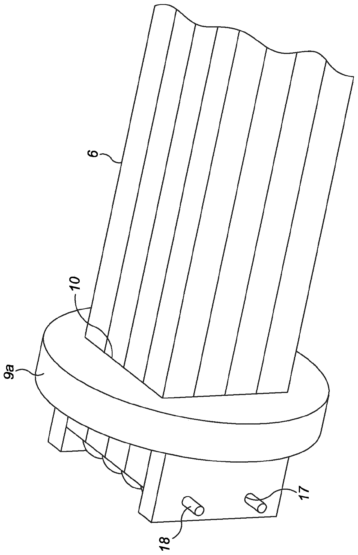
[0046] refer to figure 1 , figure 2 and image 3 , the electric heater 1 comprises a housing 2 in the form of a cylindrical sheath 3 (having an inwardly facing surface 3b and an outwardly facing surface 3a, respectively), which defines a housing which is open at both axial ends. Internal chamber 4. A heating assembly generally indicated by reference numeral 5 is mounted within the chamber 4 . The heating assembly 5 consists of a plurality of longitudinally elongated jacket elements 6 assembled and held together to form a longitudinally elongated jacket block 7 . Each elongated jacket element 6 includes a longitudinally extending longitudinal bore 8 extending the entire length of each jacket element 6 so that between the first axial end 7a and the second axial end 7a of the jacket block 7 The two axial ends are open at the end 7b. The jacket element 6 and the jacket block 7 are formed as hollow bodies in which a solid mass and volume extend continuously between a first axia...


PUM


Abstract

An electric heater to heat a flow of a fluid has a jacket block comprising a plurality of longitudinal bores to allow the through-flow of a gas phase medium. An elongate heating element extends through each of the bores and is positionally stabilized relative to the jacket block via at least one support member, optionally in the form or an elongate rod to inhibit undesirable independent axial and / or lateral movement of the heating element relative to the jacket block.

Description

technical field [0001] The present invention relates to an electric heater for heating a flow of fluid, and in particular but not exclusively to an electric heater having at least one support member to inhibit passage of Axial and / or lateral movement of the heating element. Background technique [0002] Electric heaters for heating gases to high temperatures typically include a tube adapted to flow the gas through and an electric heating element positioned within the tube to follow the gas flow into the open first end of the tube, past the wires and then through the open The second end flows out of the tube transferring heat to the gas. [0003] Typically, a relatively thin wire is wound in a helical configuration within the tube such that the heating effect is achieved by passing an electrical current through the wire as the gas flows through the tube. Thus, the efficiency of conversion of electrical energy to thermal energy (via the heating wire) depends eg on the availa...

Claims


Application Information

Patent Timeline
Patent Type & Authority Applications(China)
IPC IPC(8): F24H3/00H05B3/42F24H1/14
CPCF24H3/002H05B3/42F24H9/1863H05B2203/003H05B2203/014H05B3/44H05B2203/022
Inventor 后藤和贵须贝聪马库斯·曼
Owner 康泰尔有限公司
Why Eureka
Try Eureka