Rear vehicle-body structure of vehicle

A vehicle and rear technology, applied in the field of rear body structure, can solve the problem of not mentioning the reinforcement frame, etc., and achieve the effects of improving handling stability, smooth load distribution, and improving surface rigidity

Active Publication Date: 2020-07-31
MAZDA MOTOR CORP
View PDF32 Cites 2 Cited by
  • Summary
  • Abstract
  • Description
  • Claims
  • Application Information

AI Technical Summary

Problems solved by technology

[0007] However, the technical solution of Patent Document 1 does not mention the specific form for ensuring the surface rigidity of the rear floor, such as the form of the reinforcement frame under the rear seat, and there is still room for discussion.

Method used


Image

  • Rear vehicle-body structure of vehicle
  • Rear vehicle-body structure of vehicle
  • Rear vehicle-body structure of vehicle

Examples


Embodiment Construction

[0037] Embodiments of the present invention will be described in detail below based on the drawings.

[0038] In the accompanying drawings, arrow F indicates the front of the vehicle, arrow R indicates the right side of the vehicle, arrow L indicates the left side of the vehicle, and arrow U indicates the top of the vehicle.

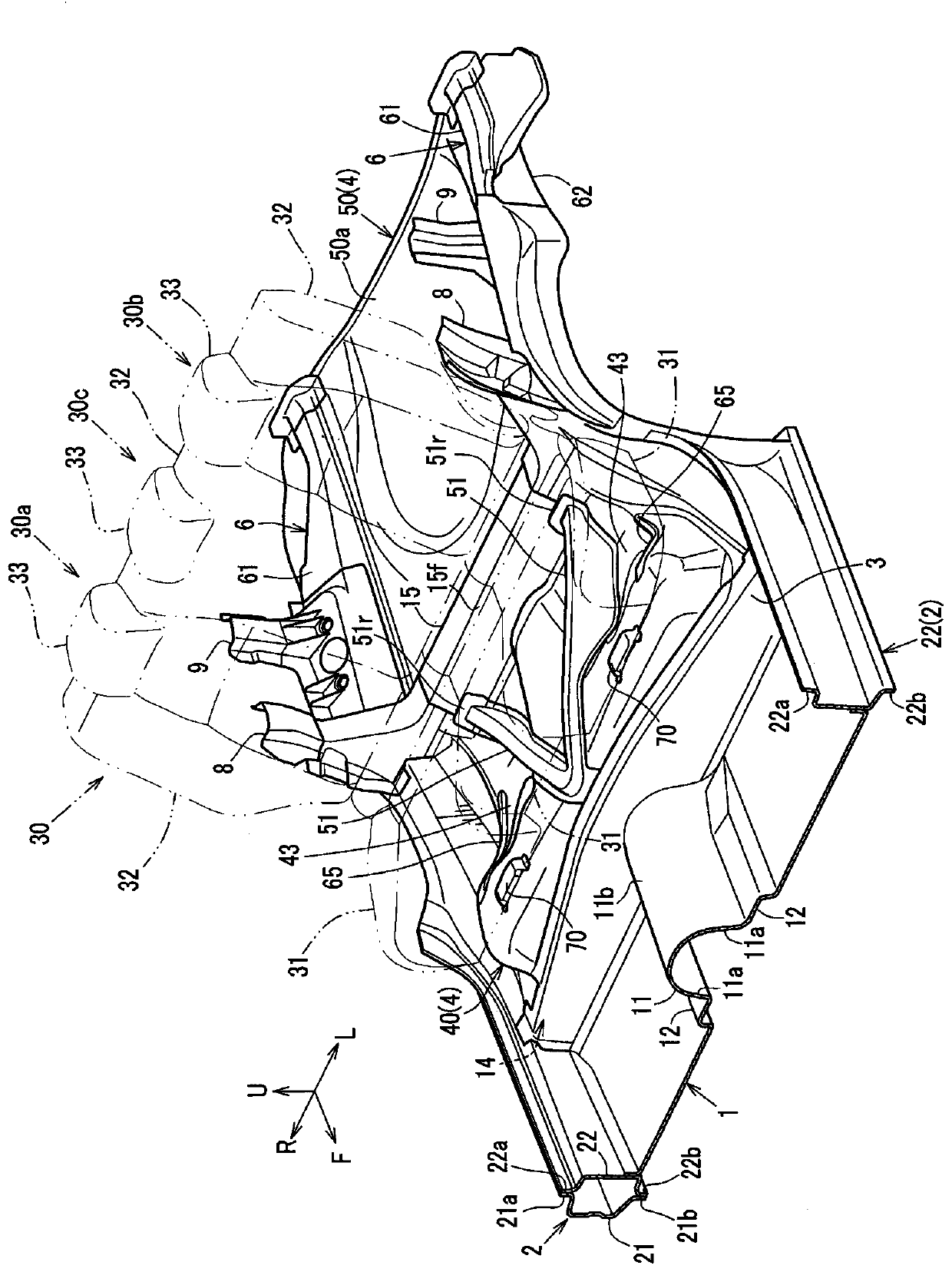
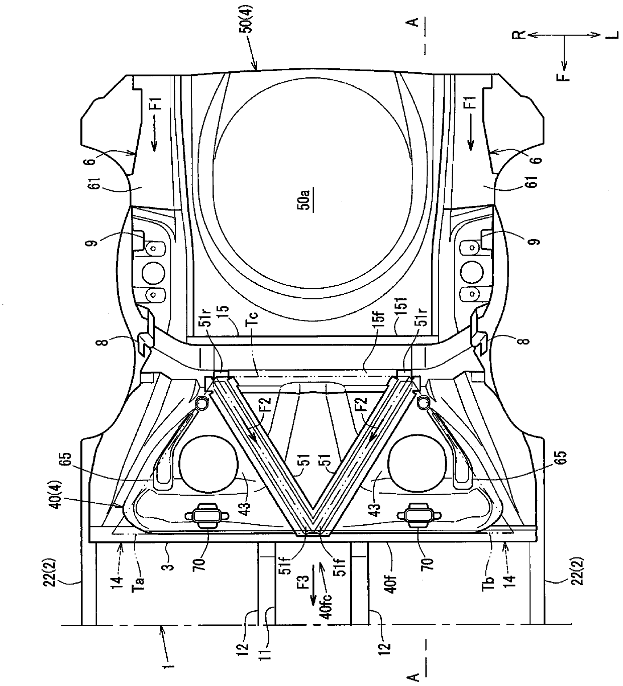
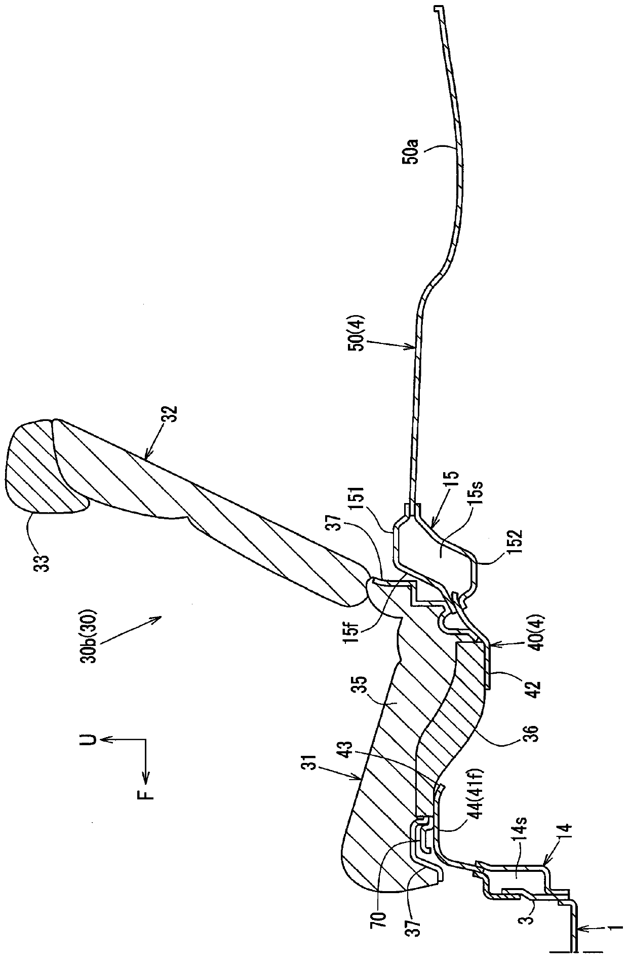
[0039] Such as figure 1 , figure 2 As shown, the vehicle body of the automobile (hereinafter simply referred to as “vehicle”) according to the present embodiment includes a floor 1 forming a floor of a cabin and side members 2 joined and fixed to both sides of the floor 1 .

[0040] At the center position in the vehicle width direction of the floor panel 1 (the floor section on the front side), a center tunnel 11 , which is a tunnel section extending forward from the rear end of the floor panel 1 , is provided.

[0041] Such as figure 1 As shown, in the central tunnel 11, the left and right side walls 11a and the upper upper plate portion 11b are int...


PUM


Abstract

The invention provides a rear vehicle-body structure in order to achieve smooth load distribution of the vehicle to the front of the vehicle when a rear collision occurs, and to improve the surface rigidity of a rear floor in the front-rear direction of the vehicle in order to achieve a force to be displaced in the front-rear direction of the vehicle generated by a rear seat when the vehicle travels. The rear vehicle-body structure of a vehicle comprises a rear-floor front part 40 on which a rear seat 30 is placed and which is inclined such that a front side thereof is located at a higher level than a rear side thereof, a pair of right-and-left reinforcements 51 which are configured such that their rear end portions 51r are positioned on both sides, in a vehicle width direction, of the rear-floor front part 40 and to extend obliquely forwardly-and-inwardly, in the vehicle width direction, from the rear end portions 51r, and a pair of right-and-left beads 65 which are provided on an outward side, in the vehicle width direction, of the pair of right-and-left reinforcements 51 and configured to extend obliquely forwardly-and-outwardly, in the vehicle width direction, from a vicinity of the rear end portions 51r of the reinforcements 51.

Description

technical field [0001] The present invention relates to a rear body structure of a vehicle provided with a forwardly rising floor on which a vehicle seat is mounted. Background technique [0002] When a collision object collides with a vehicle such as a car from the rear (rear side collision), in order to disperse and absorb the collision load from the rear (rear side collision load), it needs to be smoothly transmitted to the front of the vehicle. For this reason, it is necessary to set the rear body structure of the vehicle so that the force transmission path from the rear of the vehicle to the front for the transmission of the rear side collision load is as smooth as possible. [0003] For example, the technical solution disclosed in Patent Document 1 is: a left and right paired reinforcing frame is provided at the central position in the vehicle width direction. Suspension towers are connected in an inclined shape. [0004] Thus, in the rear body structure of the vehic...

Claims


Application Information

Patent Timeline
Patent Type & Authority Applications(China)
IPC IPC(8): B62D25/20
CPCB62D25/20B62D25/2027B62D21/15B60N2/005B62D21/09
Inventor 塚本英行益田晃义松下幸治
Owner MAZDA MOTOR CORP
Why Eureka
Try Eureka