Lens structure, camera, terminal and control method thereof, and computer storage medium
A control method and camera technology, applied in installation, optics, instruments, etc., can solve the problems of large lens size and unreliable structure
- Summary
- Abstract
- Description
- Claims
- Application Information
AI Technical Summary
Problems solved by technology
Method used
Image

Examples
no. 1 example
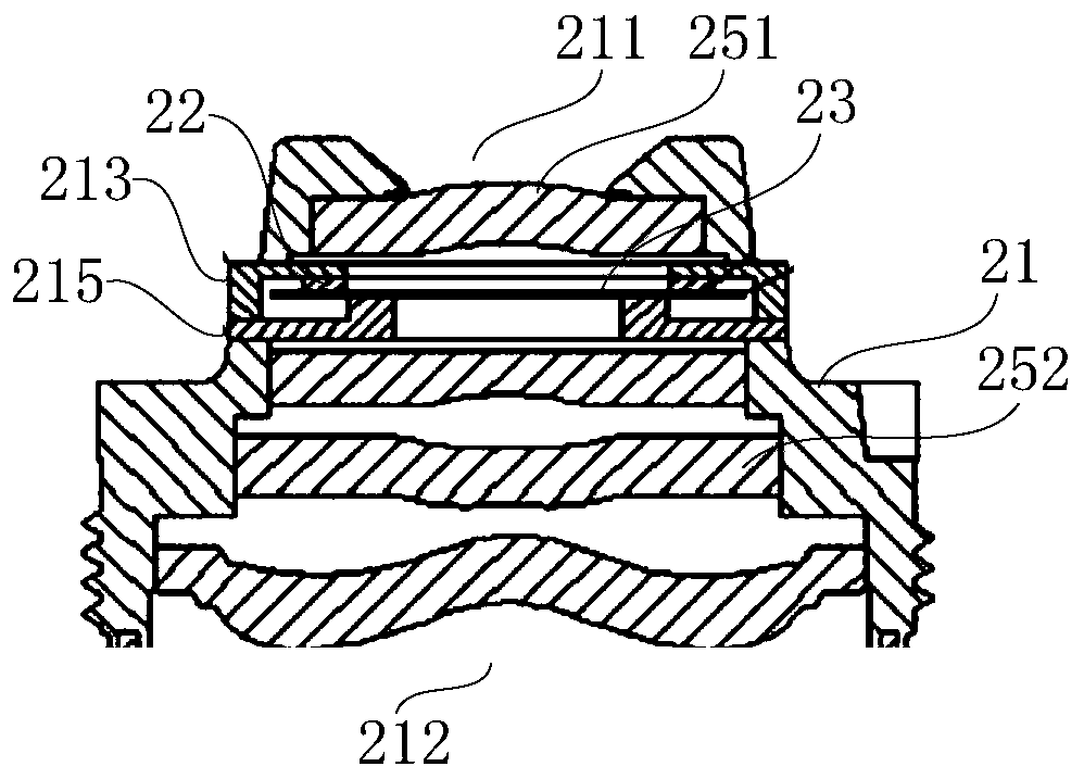
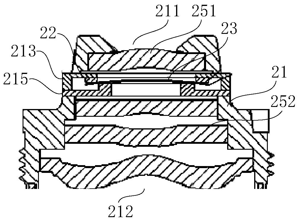
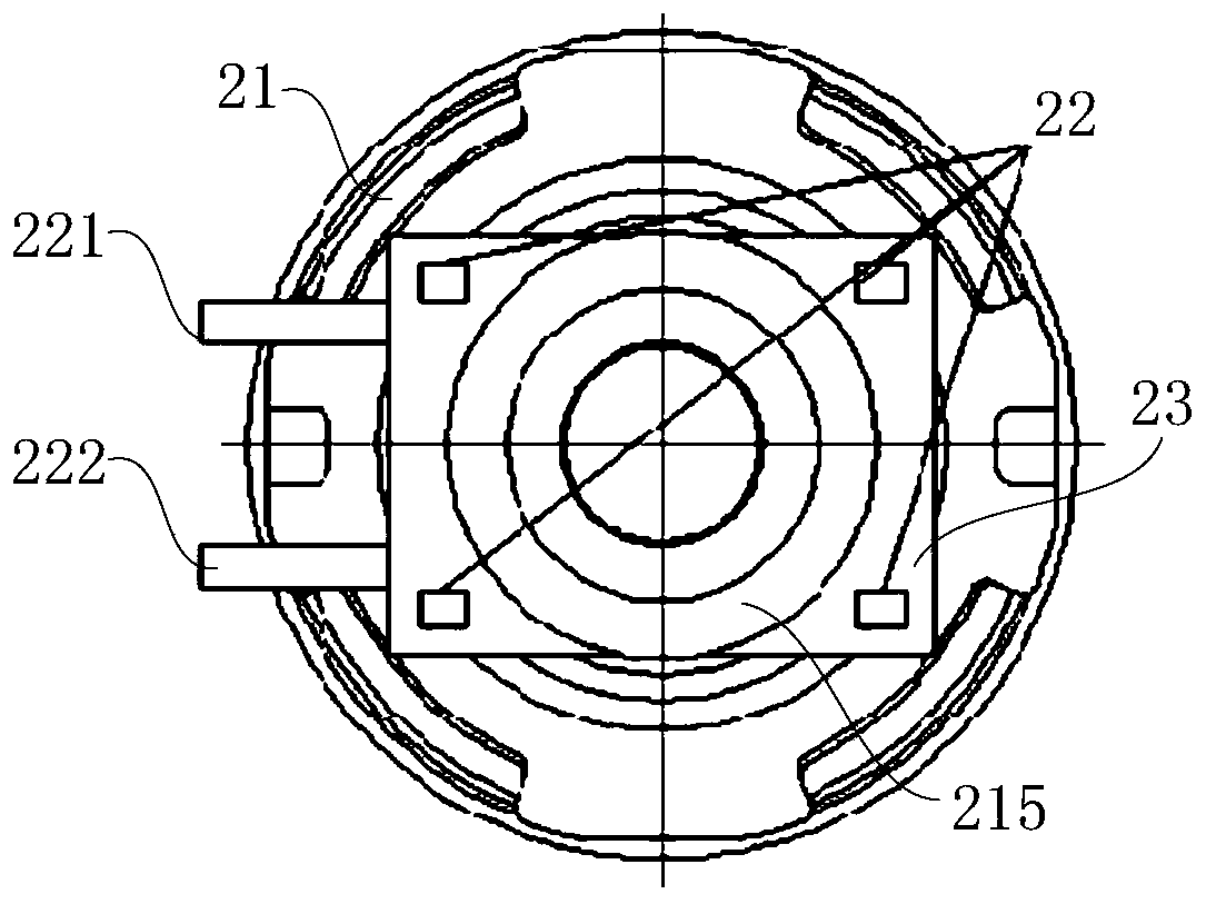
[0049] figure 1 is a structural schematic diagram of the lens structure shown according to the first embodiment. Please refer to figure 1 The lens structure of this embodiment includes a lens barrel 21, a driver 22 and a flexible transparent sheet 23, the flexible transparent sheet 23 is arranged in the optical path in the lens barrel 21, and the driver 22 is used to drive the flexible transparent sheet 23 to deform to Change the focal length. Since the focal length can be changed only by driving the flexible light-transmitting sheet 23 built in the lens barrel 21 to deform, the structure is simple and the size of the lens can be reduced. In addition, the built-in structure is more stable and reliable.
[0050]The lens barrel 21 is a multi-step cylindrical structure, the small aperture end is the light entrance 211, the large aperture end is the light exit 212, the light entrance 211 is provided with a first lens 251, and there is a gap between the first lens 251 and the lig...
no. 2 example
[0058] Figure 4 is a partial structural schematic diagram of the lens structure shown according to the second embodiment. Please refer to Figure 4 , Figure 4 Only the matching structure between the first bracket 313, the second bracket 315, the driving member 32 and the flexible light-transmitting sheet 33 is shown. The main differences between the lens structure of this embodiment and the first embodiment are:
[0059] The first bracket 313 is far away from the light entrance of the lens barrel relative to the second bracket 315 (refer to figure 1 The light entrance 211) in the lens barrel is set, the driver 32 is fixed on the side of the first bracket 313 facing the light entrance of the lens barrel, and the second support 315 abuts against a side of the flexible light-transmitting sheet 33 facing the light entrance of the lens barrel On the other hand, the contact point between the second bracket 315 and the flexible transparent sheet 33 is closer to the center of the...
no. 3 example
[0064] Image 6 is a schematic structural diagram of the camera according to the third embodiment. Please refer to Image 6 The camera head of this embodiment includes the lens structure described in the first embodiment. When the lens structure described in the first embodiment is applied, the camera head of this embodiment can realize the adjustment between the standard focal length and the short focal length.
[0065] The camera also includes a photosensitive element 46 and a circuit board 47. The photosensitive element 46 is arranged on the light outlet of the lens barrel 41, and the light entering from the light inlet 411 of the lens barrel 41 enters the photosensitive element through the adjustment of each lens and the flexible light-transmitting sheet 43. 46 generates photosensitive signals, which are processed by chips on the circuit board 47 to generate images.
[0066] When a short focal length is required, such as Figure 7 As shown, the control driver 42 pushes ...
PUM
 Abstract
Description
Claims
Application Information
 - R&D
- Intellectual Property
- Life Sciences
- Materials
- Tech Scout
- Unparalleled Data Quality
- Higher Quality Content
- 60% Fewer Hallucinations
Browse by: Latest US Patents, China's latest patents, Technical Efficacy Thesaurus, Application Domain, Technology Topic, Popular Technical Reports.
© 2025 PatSnap. All rights reserved.Legal|Privacy policy|Modern Slavery Act Transparency Statement|Sitemap|About US| Contact US: help@patsnap.com