Numerically-controlled machine tool positioning structure for motor machining

A technology of CNC machine tool and positioning structure, which is applied to metal processing mechanical parts, positioning devices, metal processing equipment and other directions, can solve the problems of cumbersome operation and affect the processing efficiency of motors, and achieve the effect of improving processing efficiency.

Inactive Publication Date: 2020-08-04
孙雪峰
View PDF11 Cites 9 Cited by
  • Summary
  • Abstract
  • Description
  • Claims
  • Application Information

AI Technical Summary

Benefits of technology

This technology allows for efficient rotation of an engine's case while being secured by two pairs of jaws made up from multiple parts connected together through hollow tubes called cables. By driving these tools towards each other at different speeds, it ensures proper alignment between them and improves overall performance of the machine. Additionally, this design makes it easy to install or process the cases without having to manually hold their position when they are fixed onto a base plate.

Problems solved by technology

This patented describes an improved design solution for machining electric cars' motors with multiple types of connections needed due to its unique feature called "teeth". Current methods involve removing the entire motor from the housing before drilling new ones, which may require significant effort during maintenance work. Therefore, the technical problem addressed by this innovative technology is how to efficiently process these connective points without requiring extensive reassembly operations after each hole being made.

Method used


Image

  • Numerically-controlled machine tool positioning structure for motor machining
  • Numerically-controlled machine tool positioning structure for motor machining
  • Numerically-controlled machine tool positioning structure for motor machining

Examples


Embodiment Construction

[0020] The following will clearly and completely describe the technical solutions in the embodiments of the present invention with reference to the accompanying drawings in the embodiments of the present invention. Obviously, the described embodiments are only some, not all, embodiments of the present invention. Based on the embodiments of the present invention, all other embodiments obtained by persons of ordinary skill in the art without creative efforts fall within the protection scope of the present invention.

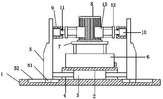
[0021] see Figure 1~3 , the present invention provides a technical solution: a positioning structure of a CNC machine tool for motor processing, including a base plate 1 fixedly installed on the CNC machine tool, a first housing 2 is arranged in the middle of the top of the base plate 1, and the first housing The left and right ends of 2 are open, the middle part of the inner cavity of the first housing 2 is provided with a double-headed hydraulic cylinder 3, the ...


PUM


Abstract

The invention discloses a numerically-controlled machine tool positioning structure for motor machining, and belongs to the technical field of motor machining devices. The structure comprises a bottomplate, the bottom plate is fixedly mounted on a numerically-controlled machine tool, a first shell is arranged in the middle of the top end of the bottom plate, openings are formed in the left end and the right end of the first shell, a double-end hydraulic oil cylinder is arranged in the middle of an inner cavity in the first shell, push-pull rods are fixedly connected to the movable ends of thetwo sides of the double-end hydraulic oil cylinder, vertical frames are slidably arranged at the top end of the bottom plate, and the two vertical frames are oppositely arranged left and right. According to the structure, the double-end hydraulic oil cylinder drives clamping pieces on the two sides to conduct clamping operation so that centering clamping on a motor shell can be effectively guaranteed; through an arranged rotating motor and other structures, the clamped motor shell can rotate to automatically adjust the machined face, and the motor shell machining efficiency is improved; and through an arranged lifting mechanism and supporting plate, the motor shell can be supported in the clamping mounting or machining process.

Description


Claims


Application Information

Patent Timeline
Owner 孙雪峰
Why Eureka
Try Eureka