Tire

A technology for tires and tire shoulders, applied to tire parts, tire tread/tread pattern, vehicle components, etc., can solve the problems of no rigidity difference, no self-aligning moment, and response lag, etc., to achieve ride comfort performance Improvement, responsiveness improvement, and the effect of riding comfort performance

Active Publication Date: 2020-08-04
SUMITOMO RUBBER IND LTD
View PDF15 Cites 0 Cited by
  • Summary
  • Abstract
  • Description
  • Claims
  • Application Information

AI Technical Summary

Problems solved by technology

[0004] However, in the pneumatic tire of Patent Document 1, there is no difference in rigidity between the vehicle outside and the vehicle inside when the vehicle is mounted, no self-aligning moment occurs, and response lag occurs during steering.

Method used


Image

  • Tire
  • Tire
  • Tire

Examples


Embodiment Construction

[0028] Hereinafter, one embodiment of the present invention will be described in detail based on the drawings.

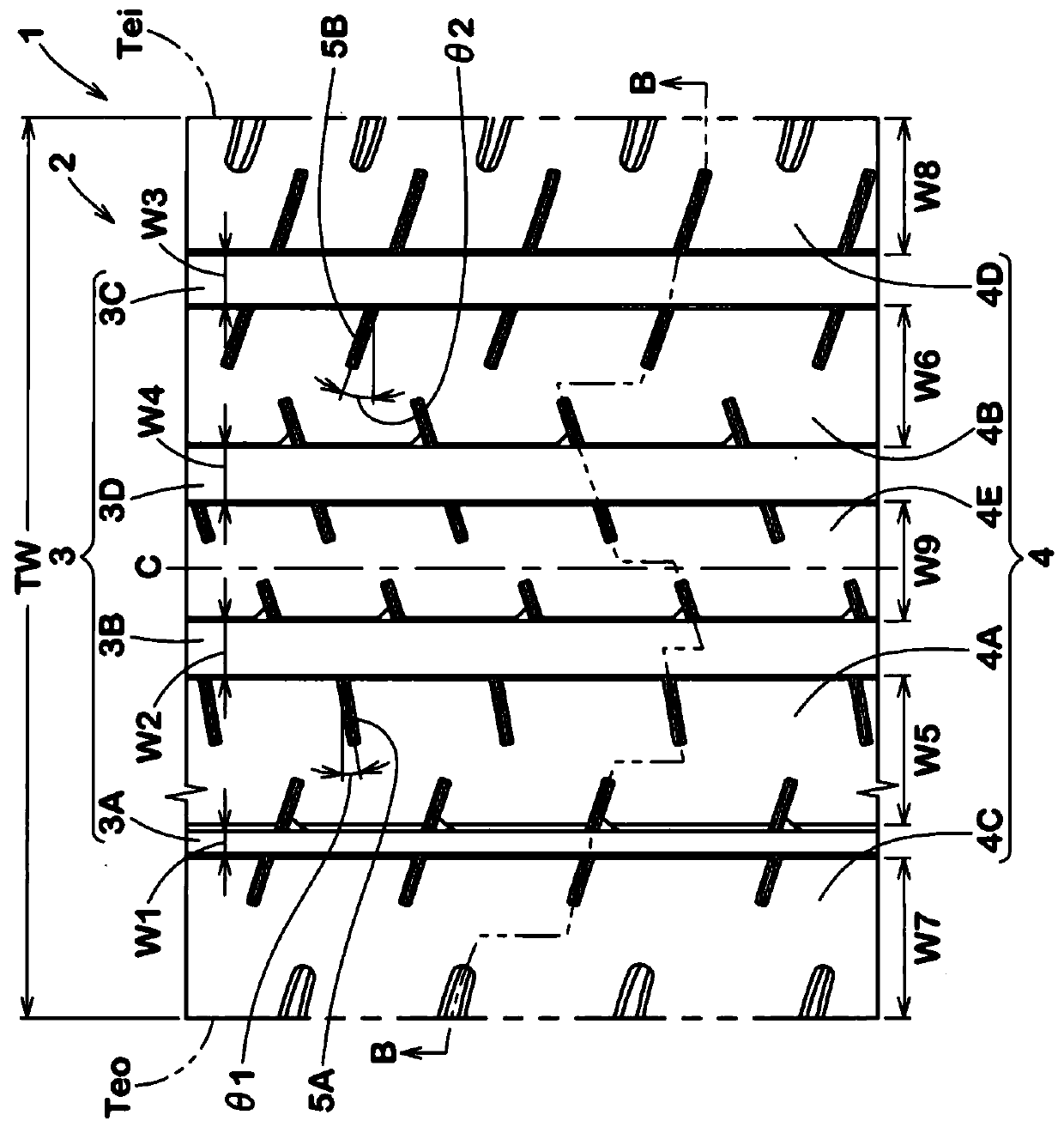
[0029] figure 1 It is a developed view showing the tread portion 2 of the tire 1 of the present embodiment. like figure 1 As shown, the tire 1 of the present embodiment has a tread portion 2 provided with an asymmetrical tread pattern designated in a direction to be mounted on a vehicle. The direction of installation to the vehicle is displayed using letters or symbols, for example, on a side wall portion (not shown).

[0030] The tire 1 is suitably used as a pneumatic tire for passenger cars, for example. The tire 1 is not limited to a pneumatic tire for passenger cars, and can be used for various tires such as a pneumatic tire for heavy loads and a non-pneumatic tire in which pressurized air is not filled inside the tire.

[0031] When the tire 1 is mounted on a vehicle, the tread portion 2 of the present embodiment has an outer tread end Teo located on the ve...


PUM


Abstract

A tire capable of achieving both steering stability and ride comfort is provided. An outer middle land portion 4A demarcated between an outer shoulder circumferential groove 3A and an outer crown circumferential groove 3B and located at an outer side of a vehicle when the tire is mounted on the vehicle, and an inner middle land portion 4B demarcated between an inner shoulder circumferential groove3C and an inner crown circumferential groove 3D and located at an inner side of the vehicle when the tire is mounted on the vehicle, are formed in a tread portion 2. The outer middle land portion 4Ahas first outer middle sipes 5A extending from the outer crown circumferential groove 3B toward the outer shoulder circumferential groove 3A and terminating within the outer middle land portion 4A. The inner middle land portion 4B has first inner middle sipes 5B extending from the inner shoulder circumferential groove 3C toward the inner crown circumferential groove 3D and terminating within the inner middle land portion 4B. An angle theta 1 of each first outer middle sipe 5A with respect to a tire axial direction is smaller than an angle theta 2 of each first inner middle sipe 5B with respectto the tire axial direction.

Description

technical field [0001] The present invention relates to a tire capable of achieving both handling stability and riding comfort. Background technique [0002] Conventionally, tires in which various required performances have been attempted to be achieved in the tire have been known. For example, the following Patent Document 1 proposes a pneumatic tire that attempts to achieve both steering stability performance and riding comfort performance by specifying the length of shoulder lug grooves and the length of shoulder sipes. [0003] Patent Document 1: Japanese Patent Laid-Open No. 2017-128269 [0004] However, the pneumatic tire of Patent Document 1 has no rigidity difference between the vehicle outside and the vehicle inside when mounted on the vehicle, does not generate self-aligning moment, and may cause response lag during steering. Therefore, further improvements are required to achieve both handling stability and ride comfort. Contents of the invention [0005] The...

Claims


Application Information

Patent Timeline
Patent Type & Authority Applications(China)
IPC IPC(8): B60C11/03B60C11/13
CPCB60C11/03B60C11/13B60C2011/0339B60C11/1204B60C11/1281B60C2011/1254B60C2011/1209B60C2011/0341B60C2011/0386B60C2011/0381B60C11/0304B60C2011/0388B60C11/1218B60C11/1236
Inventor 滨冈花菜子
Owner SUMITOMO RUBBER IND LTD
Why Eureka
Try Eureka