Eureka AIR delivers breakthrough ideas for toughest innovation challenges, trusted by R&D personnel around the world.

Daily maintenance method for printing roller

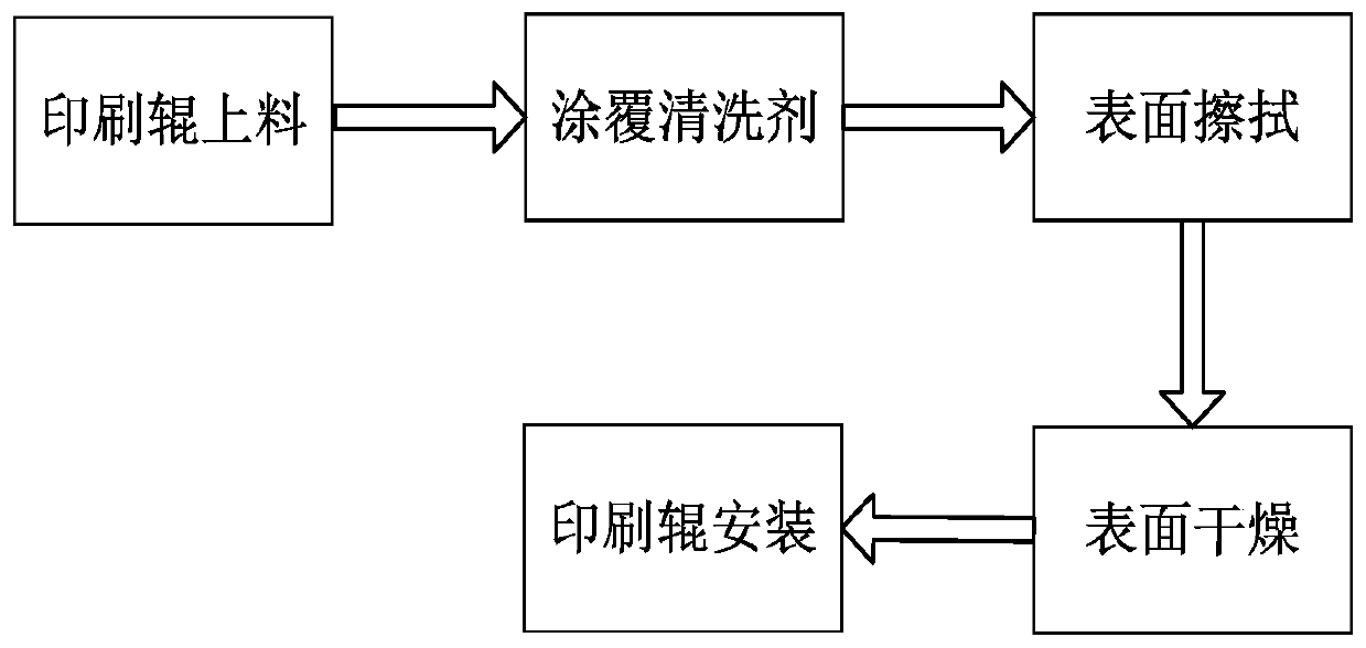
A technology for daily maintenance and printing rollers, applied in printing, printing machines, general parts of printing machinery, etc., can solve the problems of inability to apply cleaning agent on the surface of printing rollers, inability to install and disassemble printing rollers, low efficiency, etc., to achieve installation and disassembly. Good effect, avoid waste of cleaning agent, improve cleaning efficiency

Inactive Publication Date: 2020-08-07
陶猛
View PDF20 Cites 4 Cited by
  • Summary
  • Abstract
  • Description
  • Claims
  • Application Information

AI Technical Summary

Problems solved by technology

[0005] The present invention can solve the problem that the existing equipment has poor maintenance effect and incomplete cleaning when maintaining the surface of the printing roller, and cannot effectively apply cleaning agent to the surface of the printing roller, which will easily cause the surface of the printing roller to be glazed after long-term use Moreover, when the existing equipment maintains the surface of the printing roller, the installation effect of the printing roller is poor, the disassembly is inconvenient, and the printing roller cannot be installed and disassembled quickly, resulting in a long maintenance period and low efficiency of the printing roller, which increases the cost of the enterprise. Production cost and other problems

Method used

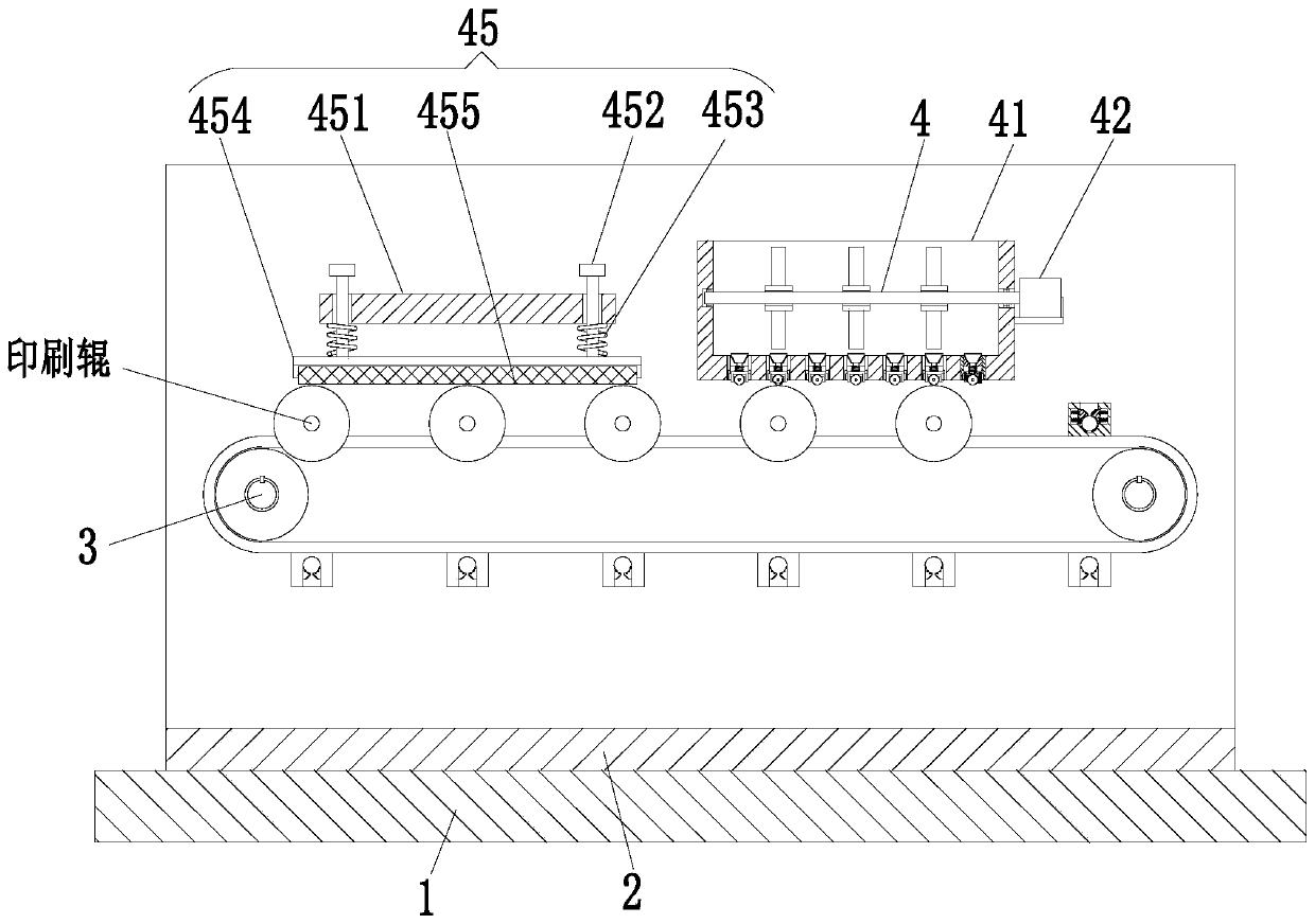
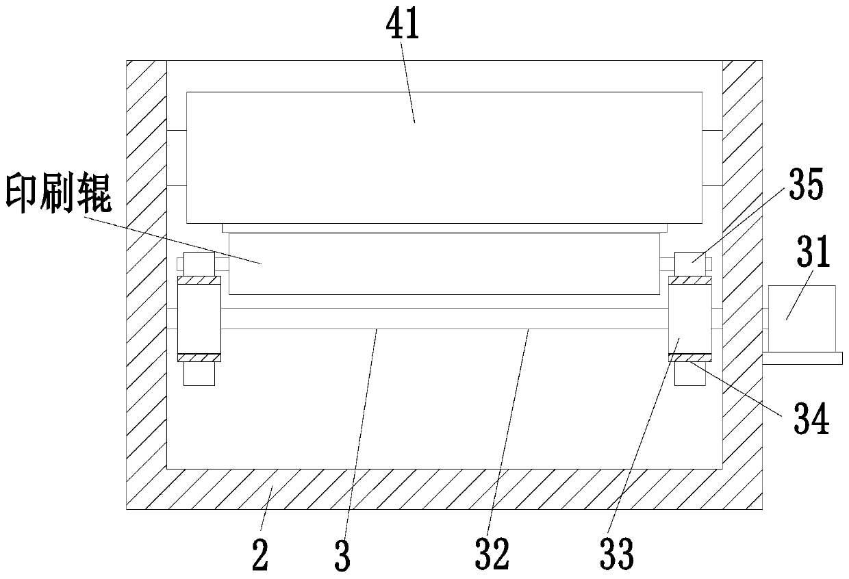

Image

  • Daily maintenance method for printing roller
  • Daily maintenance method for printing roller
  • Daily maintenance method for printing roller

Examples


Embodiment Construction

[0035] The embodiments of the present invention will be described in detail below with reference to the accompanying drawings, but the present invention can be implemented in many different ways defined and covered by the claims.

[0036] Such as Figure 1 to Figure 7 As shown, a printing roller daily maintenance method, the printing roller daily maintenance method adopts the following processing equipment, the processing equipment includes a bottom plate 1, a support frame 2, a conveying device 3 and a cleaning device 4, and the upper end of the bottom plate 1 is installed There is a support frame 2, the support frame 2 has a U-shaped structure, a conveying device 3 is installed inside the support frame 2, and a cleaning device 4 is arranged on the conveying device 3, and the cleaning device 4 is installed in the support frame 2.

[0037] The conveying device 3 includes a driving motor 31, a rotating shaft 32, a rotating roller 33, a conveyor belt 34 and a clamping seat 35. T...


PUM


Abstract

The invention relates to a daily maintenance method for a printing roller. The daily maintenance method for the printing roller is characterized by adopting machining equipment: a bottom plate, a support frame, a conveying device and a cleaning device; the support frame is arranged at the upper end of the bottom plate and is of a U-shaped structure; the conveying device is arranged in the supportframe; and the cleaning device is arranged on the conveying device and is installed in the support frame. The daily maintenance method for the printing roller can solve the problems: when existing equipment is used for maintaining the surface of the printing roller, the maintenance effect is poor, the cleaning is incomplete, a cleaning agent cannot be effectively applied to the surface of the printing roller, and the surface of the printing roller is prone to being glazed after being used for a long time; and the printing roller is poor in mounting effect and inconvenient to dismount, and cannot be quickly mounted and dismounted so that long maintenance period and low maintenance efficiency of the printing roller are caused, and the production cost of enterprises is increased.

Description

technical field [0001] The invention relates to the field of printing roller protection, in particular to a daily maintenance method for printing rollers. Background technique [0002] Before and after printing, the printing roller must be cleaned with a special cleaning agent to keep the surface of the printing roller clean. If the cleaning is not in place, the surface of the printing roller will be glazed, resulting in ink affinity and ink transfer of the printing roller. Reduced, and even cause deinking. Glazing increases the surface hardness and decreases the elasticity of the printing roller, and at the same time accelerates the wear of the printing roller, resulting in pits and cracks on the rubber surface, resulting in dross and affecting the printing quality. [0003] At present, the existing printing rollers usually have the following defects in the maintenance process: 1. When the existing equipment maintains the surface of the printing roller, the maintenance eff...

Claims


Application Information

Patent Timeline
Patent Type & Authority Applications(China)
IPC IPC(8): B41F35/02B41F27/00
CPCB41F27/00B41F35/02
Inventor 陶猛夏可欣
Owner 陶猛
Why Eureka
Eureka Blog
Learn More