
Directional drilled hole water draining device for mine

A technology for directional drilling and mines, which is used in safety devices, drainage, gas discharge, etc., can solve the problems of water blockage in directional drilling, affecting the drainage effect of directional drilling, and unable to meet the requirements of water discharge in directional drilling. The effect of water accumulation and water discharge is remarkable, and the effect of reducing the workload of manual waterproofing and patrolling

Pending Publication Date: 2020-08-07
HUAIBEI MINING IND
View PDF0 Cites 0 Cited by
  • Summary
  • Abstract
  • Description
  • Claims
  • Application Information

AI Technical Summary

Problems solved by technology

[0002] At present, the sandstone fissure water on the roof of the working face in the mine is developed and enriched, resulting in a large amount of water in the directional drainage drilling of the working face. If the water is not released in time, the directional drilling drainage effect will be affected, and even the directional drilling water plugging will cause gas in the drilling site. Abnormally, the previous water discharge bag device can no longer meet the water discharge requirements of directional drilling, so the previous installation mode of the water discharge bag is changed, the high and low pipes of the directional drilling are processed, and the secondary water discharge is performed, and the manual water discharge is changed to automatic water discharge to ensure no water in the directional drilling The blocking phenomenon is of great significance

Method used


Image

  • Directional drilled hole water draining device for mine

Examples


Embodiment Construction

[0025] The purpose of the present invention can be achieved through the following technical solutions:

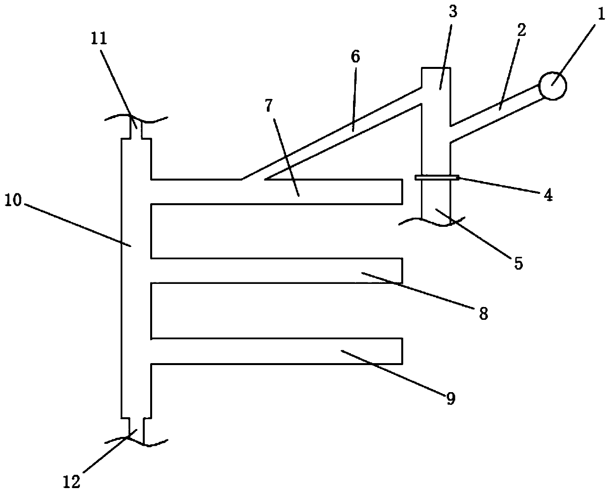
[0026] A kind of directional drilling water release device for mine, see figure 1 , including the first inclined branch pipe 2, the high and low pipes 3, the valve 4, the first discharge pipe 5, the second inclined branch pipe 6, the first pumping and collecting pipe 7, the second pumping and collecting pipe 8, and the third pumping and collecting pipe 9 , extraction pipe 10, main pipe connecting pipe 11, automatic drainer connecting pipe 12;

[0027] The first inclined branch pipe 2 is connected to the first pumping and collecting pipe 7 through the high and low pipes 3 and the second inclined branch pipe 6, and the first pumping and collecting pipe 7 is connected to the main pipe connecting pipe 11; the high and low pipes 3 are provided with a first The drain pipe 5; the extraction pipe 10 is provided with an automatic water drain connecting pipe 12;

[0028] The side w...


PUM


Abstract

The invention discloses a directional drilled hole water draining device for a mine. The device comprises a first inclined branch pipe, a high-low pipe, a valve, a first water draining pipe, a secondinclined branch pipe, a first extracting collecting pipe, a second extracting collecting pipe, a third extracting collecting pipe, an extracting pipe, a main pipe connecting pipe and an automatic water draining device connecting pipe; the first inclined branch pipe is connected to the first extracting collecting pipe through the high-low pipe and the second inclined branch pipe, and the first extracting collecting pipe is connected with the main pipe connecting pipe; the first water draining pipe is arranged on the high-low pipe; the automatic water draining device connecting pipe is arrangedon the extracting pipe; the first inclined branch pipe and the second inclined branch pipe are arranged on the side wall of the high-low pipe; the valve is arranged at the bottom end of the high-low pipe; and the first water draining pipe is arranged below the valve. The device has the characteristics that the problem about water accumulation of a directional drilled hole is effectively solved, the effects of automatic water flowing and automatic water discharging are achieved, the water discharging effect is remarkable, and the workload of regular manual water prevention and patrol of manpower is reduced.

Description

technical field [0001] The invention relates to a directional drilling water discharge device for mines, especially a device that effectively solves the problem of directional drilling water accumulation, realizes the effect of self-flowing water and automatic water discharge, has a remarkable water discharge effect, and reduces the workload of manpower, regular manual waterproofing and patrolling Directional drilling water release device for mine. Background technique [0002] At present, the sandstone fissure water on the roof of the working face in the mine is developed and enriched, resulting in a large amount of water in the directional drainage drilling of the working face. If the water is not released in time, the directional drilling drainage effect will be affected, and even the directional drilling water plugging will cause gas in the drilling site. Abnormally, the previous water discharge bag device can no longer meet the water discharge requirements of directiona...

Claims


Application Information

Patent Timeline
Patent Type & Authority Applications(China)
IPC IPC(8): E21F16/00E21F7/00
CPCE21F7/00E21F16/00
Inventor 陈富利吉洪涛王华田张飞
Owner HUAIBEI MINING IND
Learn More