
Sensor parameter optimization method and device, controller and medium

A sensor parameter and optimization method technology, which is applied in the direction of measuring devices, instruments, and volume/mass flow generated by electromagnetic effects, can solve the problems of affecting the measurement accuracy of electromagnetic flow sensors, consuming a lot of material and financial resources, and difficult to grasp the accuracy. The effect of saving manpower and material resources, low cost, and extensive use of value

Active Publication Date: 2022-08-09
ZHUHAI HETIAN ELECTRONICS TECH
View PDF6 Cites 0 Cited by
  • Summary
  • Abstract
  • Description
  • Claims
  • Application Information

AI Technical Summary

Problems solved by technology

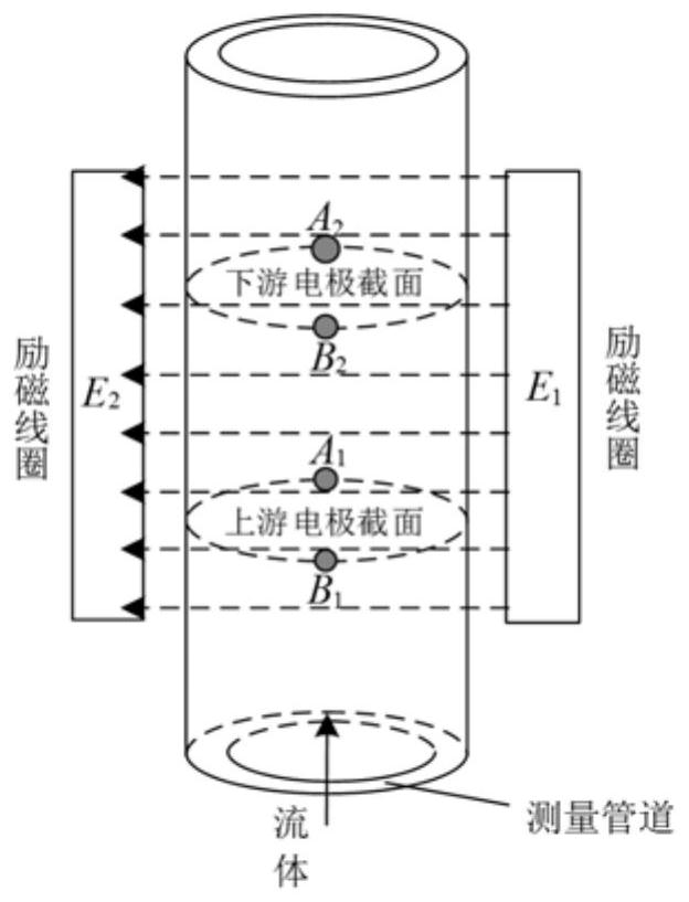
The horizontal distance and vertical distance between the detection electrodes of the electromagnetic flow sensor, that is, the horizontal spacing of the electrodes and the longitudinal spacing of the electrodes is one of the key technologies to realize the electromagnetic flow sensor. The setting of the horizontal spacing of the electrodes and the longitudinal spacing of the electrodes will directly affect the electromagnetic flow sensor. For example, when the distance between the upstream electrode and the downstream electrode is large, the upstream electrode and the downstream electrode will not be in the same magnetic field, and eddy currents will be generated, resulting in measurement errors
Simply changing the electrode structure parameters through experience to optimize the parameters of the electromagnetic flow sensor will consume a lot of material and financial resources, and the accuracy is difficult to grasp. Therefore, how to realize the parameter optimization of the electromagnetic flow sensor has become an urgent technical problem to be solved.

Method used


Image

  • Sensor parameter optimization method and device, controller and medium
  • Sensor parameter optimization method and device, controller and medium
  • Sensor parameter optimization method and device, controller and medium

Examples


Embodiment Construction

[0081] In order to further illustrate the technical means and effects adopted by the present invention to achieve the predetermined purpose of the invention, the following describes the specific method and device for optimizing sensor parameters, the controller and the medium according to the present invention with reference to the accompanying drawings and preferred embodiments. Embodiments and their effects are described in detail as follows.

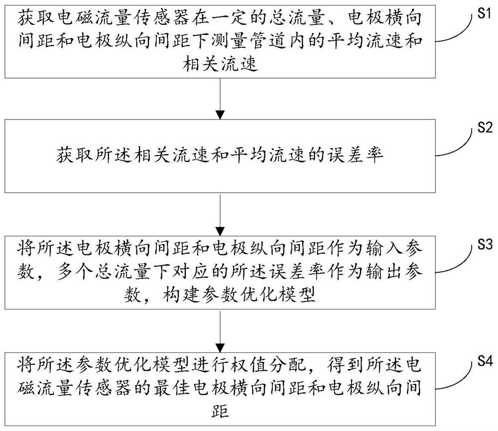
[0082] The embodiment of the present invention provides a sensor parameter optimization method, which is applied to an electromagnetic flow sensor, such as figure 1 shown, including the following steps:

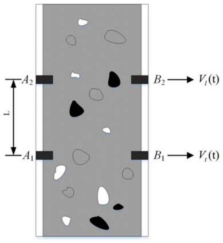
[0083] Step S1: Obtain the average flow velocity and related flow velocity in the measuring pipeline of the electromagnetic flow sensor under a certain total flow, electrode lateral spacing and electrode longitudinal spacing, wherein the electrode lateral spacing is the inner diameter of the measuring pipeline, and the electrode long...


PUM


Abstract

The invention relates to a sensor parameter optimization method and device, a controller and a medium, which are applied to an electromagnetic flow sensor. The method includes: obtaining the electromagnetic flow sensor under a certain total flow, electrode lateral spacing and electrode longitudinal spacing to measure the flow rate in the pipeline. Average flow velocity and relative flow velocity; obtain the error rate of the relative flow velocity and average flow velocity; take the electrode lateral spacing and electrode longitudinal spacing as input parameters, and the corresponding error rates under multiple total flow rates as output parameters, and build parameter optimization model; the parameter optimization model is weighted to obtain the optimal horizontal electrode spacing and longitudinal electrode spacing of the electromagnetic flow sensor. The invention obtains the optimal parameters of the electromagnetic flow sensor by analyzing the error rate of the relative flow velocity and the average flow velocity under a plurality of total flow rates, with short time and low cost.

Description

technical field [0001] The invention relates to the technical field of electromagnetic flow sensors, in particular to a method and device for optimizing sensor parameters, a controller and a medium. Background technique [0002] An electromagnetic flow sensor is an instrument that detects the volume flow of fluid flowing through the sensor based on Faraday's law of electromagnetic induction, for example, it can be used to measure downhole flow. Since the inside of the electromagnetic flowmeter pipeline is smooth and unobstructed, it will not interfere with the fluid flow, and will not produce pressure loss, and the measurement results have nothing to do with the physical parameters such as the temperature, viscosity, and pressure of the measured fluid. Therefore, the electromagnetic flow sensor is an accurate measurement of downhole Multiphase flow provides effective technical support, such as downhole oil, gas and water three-phase flow. The correlation method can be used ...

Claims


Application Information

Patent Timeline
Patent Type & Authority Patents(China)
IPC IPC(8): G01F1/58G01F15/00
CPCG01F1/58G01F15/00
Inventor 李英伟杨韵桐马少卿张玉辉王延军李雷刘兴斌谢荣华
Owner ZHUHAI HETIAN ELECTRONICS TECH
Learn More