
Bottom foot combined part

A technology of assembly and foot, applied in the parts, instruments, casings and other directions of the instrument, can solve the problems of low reliability, reduced positioning accuracy, low positioning accuracy, etc., and achieve high-reliable installation, precise positioning, and high-reliable load bearing. Effect

Pending Publication Date: 2020-08-07
西安现代控制技术研究所
View PDF0 Cites 0 Cited by
  • Summary
  • Abstract
  • Description
  • Claims
  • Application Information

AI Technical Summary

Problems solved by technology

When the equipment and the feet are connected by welding, the disadvantages are: the high heat generated during welding can easily cause deformation of the plate, resulting in low positioning accuracy. difficulty
When the screw connection is used between the equipment and the foot, the disadvantage is that the impact and vibration loads of the base are transmitted to the equipment through the screws, the reliability is relatively low and the overall strength advantage of the foot material cannot be brought into play. The fit gap will also reduce the positioning accuracy, and the application is limited in occasions that require higher positioning accuracy

Method used


Image

  • Bottom foot combined part
  • Bottom foot combined part
  • Bottom foot combined part

Examples


Embodiment Construction

[0032] In order to make the purpose, content, and advantages of the present invention clearer, the specific implementation manners of the present invention will be further described in detail below in conjunction with the accompanying drawings and embodiments.

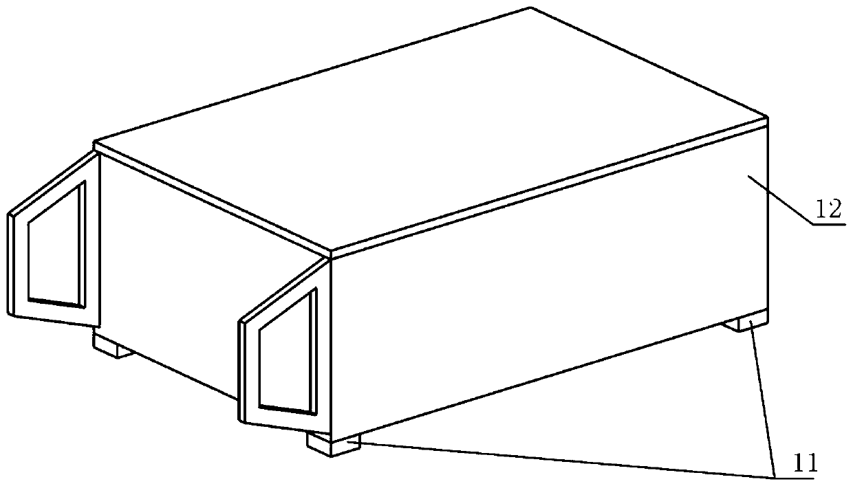
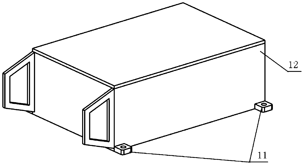
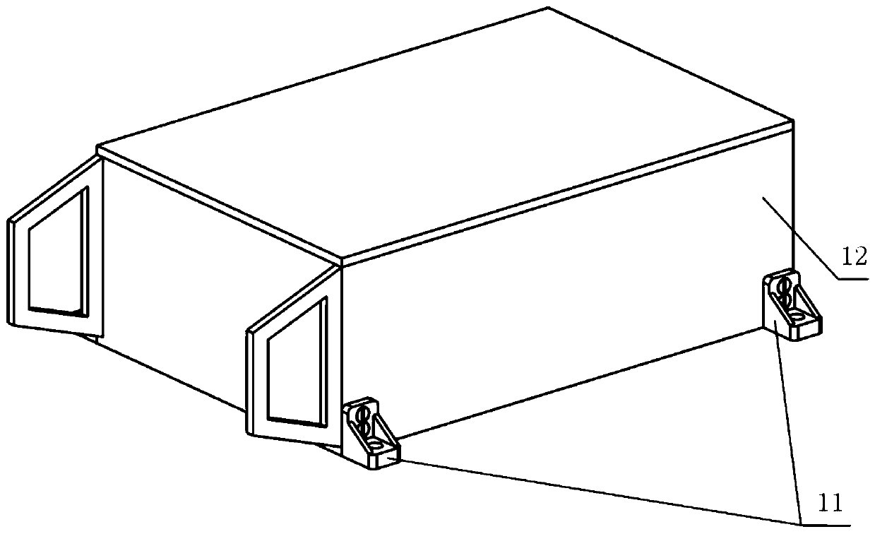
[0033] In order to solve the problems of the prior art, the present invention provides a foot assembly, such as Figure 2(a) to Figure 4(b) As shown, the foot assembly is used to be installed on the equipment casing, and the equipment casing is positioned and fixed, and the coordinate system for the installation process of the foot assembly and the equipment casing is defined as follows:

[0034] Define that the vertical direction of the device housing is upwards as the positive direction of the Z axis, the vertical direction is downwards as the negative direction of the Z axis, the left direction is the positive direction of the X axis, the right direction is the negative direction of the X axis, and the forward directi...


PUM


Abstract

The invention belongs to the technical field of instrument equipment and particularly relates to a bottom foot combined part. The bottom foot combined part is installed on the corner position of the side face or the bottom face of instrument equipment, has the functions of supporting, fixed connecting and the like, meanwhile has the function of accurate positioning and can be applied to electronicequipment or other various application occasions having high requirements for reliability and butt joint precision. The bottom foot combined part can be integrally connected with an installation basebody, the functions of supporting, fixed connecting and the like are achieved, and meanwhile the positioning function is achieved. Due to the fact that a positioning boss is arranged on the edge of abottom foot and a positioning matched structure is formed by the positioning boss and the instrument equipment at an installation connector part, corresponding part of the freedom degrees of the instrument equipment can be limited; and due to the fact that multiple bottom foot parts which are mirror image bodies mutually are used in combination with one another, the six freedom degrees of the instrument equipment in three directions of the space can be completely limited, and reliable and accurate connection between the equipment and the installation base body is finally achieved.

Description

technical field [0001] The invention belongs to the technical field of instruments and equipment, and in particular relates to a foot assembly, which is installed on the side of the instrument or at the corner of the bottom surface to play the role of supporting and fixing, and at the same time has the function of precise positioning, and can be applied to electronic equipment or Various other applications that have high requirements for reliability and docking accuracy. Background technique [0002] According to the definition in Article 4.3.42 of the national standard GB / T8582-2008 "Terms for Mechanical Structure of Electrical and Electronic Equipment", the foot is "a component that supports the casing and prevents it from directly contacting the placement surface". The foot is usually installed at the bottom of the instrument and equipment, and plays the role of supporting and fixing between the instrument and the installation base, and can also have a positioning functio...

Claims


Application Information

Patent Timeline
Patent Type & Authority Applications(China)
IPC IPC(8): G12B9/04G12B9/02G12B5/00
CPCG12B5/00G12B9/02G12B9/04
Inventor 任立力武小舟侯新宇黄超凡刘峻池梅熹文
Owner 西安现代控制技术研究所
Learn More