Forming method of ultra-high-strength pile foundation filled with waste slag

An ultra-high-strength, pile-based technology, applied in sheet pile walls, infrastructure engineering, construction, etc., can solve the problems of inability to realize centrifugal forming of concrete by strong tension and pulling of steel cages, low compactness of concrete precast piles, and high pile-making costs. , to achieve the effect of high density, high strength and improved bearing capacity

Active Publication Date: 2016-04-27
浙江兆弟技术有限公司
View PDF6 Cites 0 Cited by
  • Summary
  • Abstract
  • Description
  • Claims
  • Application Information

AI Technical Summary

Problems solved by technology

This patent is actually a kind of grouting pile. Its disadvantages are: firstly, the construction progress is slow, time-consuming and labor-intensive, and the cost of pile making is high; Pulling and centrifugal forming of concrete, so the formed concrete prefabricated pile has low density and bearing capacity is far lower than that of strong tensile prefabricated pile

Method used


Image

  • Forming method of ultra-high-strength pile foundation filled with waste slag
  • Forming method of ultra-high-strength pile foundation filled with waste slag
  • Forming method of ultra-high-strength pile foundation filled with waste slag

Examples


Embodiment 1

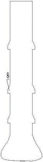
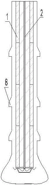
[0011] Embodiment 1: with reference to attached Figure 1-4 . A method for forming a super-high-strength pile foundation filled with waste slag. When drilling a pile foundation, according to the material of the geological structure layer, a reaming drill bit suitable for the material of the geological structure layer is used to drill the hole until the non-powdered layer is drilled, and the hole is expanded in different geological layers. The hole drill bit drills and expands one or more annular grooves 8, and then the multi-section prefabricated piles 1 are sequentially butted into the drilled pile foundation holes, and the waste slag filling material is forcibly filled into the prefabricated pile body as the prefabricated piles 1 enter. At the same time in the surrounding pile foundation holes, the multi-section grouting pipes 2 in the multi-section prefabricated piles are connected sequentially, and then the high-pressure concrete slurry is discharged from the outlet at the...

Embodiment 2

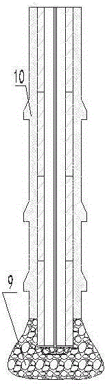
[0012] Embodiment 2: On the basis of Embodiment 1, the high-pressure concrete slurry is discharged from the outlet of the lower end of the vertical grouting pipe 2, and a part of the concrete is extruded from the basin-shaped grouting plate 4 and then injected downward into the foundation to form a head expansion pile The head 9 and a portion of concrete are extruded from the basin-shaped grouting disc 4 and turned up along the outer wall of the prefabricated pile to form a pile body wall 10 .


PUM


Abstract

The invention relates to a shaping method for a waste-residue fill ultrahigh strength pile foundation. During pile foundation drilling, a reaming drill bit adapted to geologic structure materials is used for drilling according to the geologic structure layer materials till an end pulverization layer, one or more annular grooves are reamed by the reaming drill bit in different geological layers, a plurality of sections of grouting precast piles are connected to be put in drilled pit foundation holes successively, waste-residue fillers enter along with the precast piles and are filled forcibly in the pit foundation holes on the periphery of the pile foundation, a plurality of sections of grouting pipes in the plurality of sections of grouting precast piles are connected successively, the moment when high-pressure concrete slurries are discharged through an outlet of the lower end of the vertical grouting pipe, a part of concrete is pressed downwards into the foundation after being extruded from a basin-shaped overturn disc, and a part of the concrete is turned upwards along the outer wall of the precast pile after being extruded from the basin-shaped overturn disc, and when the pressure of upward turned concrete around the outer wall of the precast pile reaches a set pressure value, high-pressure grouting is completed, the grouting pipe is pulled out, waste residues are filled in a precast pile core, and the pile foundation is shaped.

Description

technical field [0001] The invention relates to a method that can not only effectively expand the friction force between prefabricated piles and foundation soil, improve the bearing capacity of prefabricated piles, but also facilitate the completion of pile connection of prefabricated piles, and realize the pressure grouting and grouting between prefabricated piles and foundation. The invention relates to a waste residue-filled ultra-high-strength pile foundation forming method, which belongs to the field of prefabricated pile foundation formation method manufacturing. Background technique [0002] CN101058979A, title "a kind of construction method of anti-pull and anti-compression prefabricated pile", is characterized in that the construction method of anti-extension and anti-compression prefabricated pile is realized through the following steps: 1. According to the design elevation and aperture of the pile on the foundation of the building 2. After the hole is formed, put ...

Claims


Application Information

Patent Timeline
Patent Type & Authority Patents(China)
IPC IPC(8): E02D5/38E02D5/48E02D5/50
Inventor 周兆弟
Owner 浙江兆弟技术有限公司
Why Eureka
Try Eureka