
Isolation switch

A technology of isolating switches and static contacts, which is applied in the direction of electric switches, air switch components, high-voltage air circuit breakers, etc. Difficult to disengage and improved safety performance

Active Publication Date: 2022-06-17
ANDELI GRP
View PDF2 Cites 1 Cited by
  • Summary
  • Abstract
  • Description
  • Claims
  • Application Information

AI Technical Summary

Problems solved by technology

[0002] The isolating switch is a switching device that is mainly used for "isolated power supply, switching operation, and connecting and cutting off small current circuits". It has no arc extinguishing function. Distance and obvious disconnection signs; when in the closed position, the switchgear that can carry the current under normal circuit conditions and the current under abnormal conditions (such as short circuit) within a specified time is generally used as a high-voltage isolation switch, that is, the rated voltage is in The working principle and structure of the isolating switch above 1kV are relatively simple, but due to the large amount of use and high reliability requirements, it has a great impact on the design, establishment and safe operation of substations and power plants. The main feature is that it has no arc extinguishing ability, and can only open and close the circuit under the condition of no load current. The entry introduces the function, characteristics, type, application, error prevention improvement, maintenance, common problems, etc. of the isolating switch.
[0003] At present, in the process of using the existing manual isolating switch, it is easy to generate arc phenomenon (arc is a kind of Gas discharge phenomenon, the instantaneous spark generated by the current passing through some insulating medium (such as air), so the staff needs to be quick and decisive in the process of closing the switch. When using too much force, there will be a certain safety hazard due to the impact between the moving contact and the static contact. , which leads to the overload of the isolation switch and the increase of the contact resistance. For this reason, we propose the isolation switch

Method used


Image

  • Isolation switch
  • Isolation switch
  • Isolation switch

Examples


Embodiment Construction

[0024] The technical solutions in the embodiments of the present invention will be clearly and completely described below with reference to the accompanying drawings in the embodiments of the present invention. Obviously, the described embodiments are only a part of the embodiments of the present invention, rather than all the embodiments. Based on the embodiments of the present invention, all other embodiments obtained by those of ordinary skill in the art without creative efforts shall fall within the protection scope of the present invention.

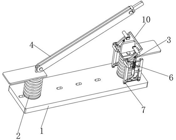
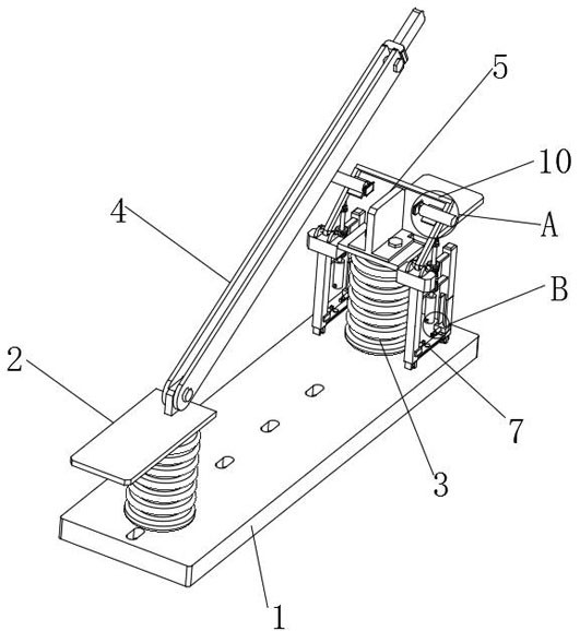
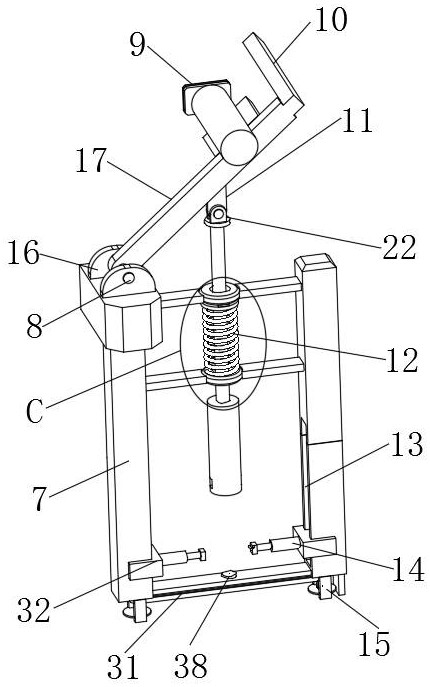
[0025] see Figure 1-7 , the present invention provides a technical solution: an isolation switch, comprising a base 1, a moving contact insulating support 2 and a static contact insulating support 3 respectively arranged on the base 1, and a moving contact installed on the moving contact insulating support 2 The body 4. The static contact body 5 installed on the static contact insulating support 3, and the moving contact is provided...


PUM


Abstract

The invention discloses an isolating switch, which comprises a base, a moving contact insulating support and a static contact insulating support respectively arranged on the base, a moving contact body installed on the moving contact insulating support, and a moving contact insulating support installed on the static contact insulating support. The static contact body, the outer side of the bottom end of the static contact body is provided with an elastic closing device for stably closing and opening the moving contact body and the static contact body, and the elastic closing device is fixedly connected to the base. For the switch, by setting an elastic closing device on the outside of the static contact body of the isolating switch, the elastic closing device can prevent the phenomenon of impact between the moving contact body and the static contact body due to excessive force when closing the switch. On the other hand, it can make stable contact between the moving contact body and the static contact body, and effectively improve the safety performance of the isolating switch.

Description

technical field [0001] The invention relates to the technical field of high-voltage switches, in particular to an isolation switch. Background technique [0002] The isolating switch is a switching device that is mainly used for "isolating the power supply, switching off operation, connecting and cutting off small current circuits" and without arc extinguishing function. Distance and obvious disconnection signs; when in the closed position, switchgear that can carry current under normal circuit conditions and current under abnormal conditions (such as short circuit) within a specified time, generally used as a high-voltage isolating switch, that is, the rated voltage is The isolation switch above 1kV has a relatively simple working principle and structure, but due to the large amount of use and high requirements for work reliability, it has a great impact on the design, establishment and safe operation of substations and power plants. The main feature is that it has no arc ...

Claims


Application Information

Patent Timeline
Patent Type & Authority Patents(China)
IPC IPC(8): H01H31/02
CPCH01H31/023H01H31/026
Inventor 向国庆刘忠陈武奇
Owner ANDELI GRP
Learn More