Slot-coupled broadband filtering antenna

A filter antenna and slot technology, applied in the field of radio frequency microwave communication, can solve the problem of low radiation gain, achieve the effect of increasing gain, avoiding loss, and widening antenna bandwidth

Active Publication Date: 2020-08-07
HUAZHONG UNIV OF SCI & TECH
View PDF7 Cites 7 Cited by
  • Summary
  • Abstract
  • Description
  • Claims
  • Application Information

AI Technical Summary

Problems solved by technology

[0004] Aiming at the defects of the prior art, the purpose of the present invention is to provide a slot-coupled filter antenna, aiming to solve the problem of low radiation gain in the existing filter antenna due to the direct introduction of the filter structure

Method used


Image

  • Slot-coupled broadband filtering antenna
  • Slot-coupled broadband filtering antenna
  • Slot-coupled broadband filtering antenna

Examples


Embodiment Construction

[0026] In order to make the object, technical solution and advantages of the present invention clearer, the present invention will be further described in detail below in conjunction with the accompanying drawings and embodiments. It should be understood that the specific embodiments described here are only used to explain the present invention, not to limit the present invention.

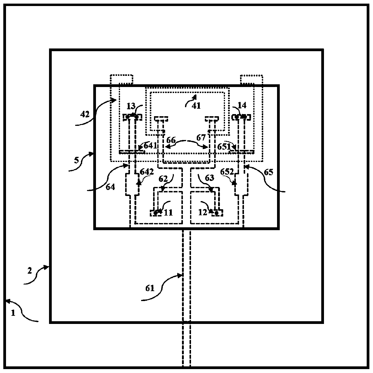
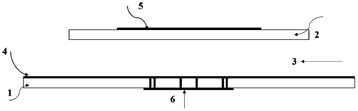
[0027] Such as figure 1 and figure 2 As shown, the present invention provides a slot-coupled filter antenna, including a feed network layer 6, a first dielectric substrate 1, a ground layer 4, a second dielectric substrate 2, and a rectangular parasitic patch 5;

[0028] The first dielectric substrate 1 is located directly below the second dielectric substrate 2, and an air layer 3 is reserved between them; the first dielectric substrate 1 is used to fix the feed network layer 6 and the ground layer 4; the second dielectric substrate 1 The second dielectric substrate 2 is used to fix the rectang...


PUM


Abstract

The invention discloses a slot-coupled filtering antenna, which comprises: a feed network layer, a first dielectric substrate, a grounding layer, a second dielectric substrate and a rectangular parasitic patch, wherein the first dielectric substrate is located below the second dielectric substrate, an air layer is reserved between the first dielectric substrate and the second dielectric substrate,the first dielectric substrate is used for fixing the feed network layer and the grounding layer, the second dielectric substrate is used for fixing the rectangular parasitic patch, the feed networklayer is located at the bottom layer of the first dielectric substrate and is used for transmitting signal energy, the grounding layer is located at the top layer of the first dielectric substrate, isprovided with a gap, and is used for coupling the energy of the feed network layer to the rectangular parasitic patch at the top layer, and the rectangular parasitic patch is located on the top layerof the second dielectric substrate and serves as a radiation unit of the antenna to be used for radiating energy to a free space. On the premise that a filtering structure is not directly introduced,the broadband filtering characteristic and the high-gain radiation characteristic of the antenna are achieved.

Description

technical field [0001] The invention belongs to the technical field of radio frequency microwave communication, and more specifically relates to a slot-coupled filter antenna. Background technique [0002] With the rapid development of wireless communication, there are more and more communication frequency bands and communication standards, which have higher and higher requirements for the RF front-end, especially the miniaturization of the RF front-end. The two most important components in the RF front-end system are the filter and the antenna. However, due to the limitation of the antenna's own radiation characteristics, the radiation performance will be affected when the antenna is miniaturized. Therefore, the miniaturization of the base station antenna itself is difficult to implement, and the miniaturization of the system can only be realized through the fusion design with the filter, so the research of the filter antenna is necessary. [0003] In recent years, there a...

Claims


Application Information

Patent Timeline
Patent Type & Authority Applications(China)
IPC IPC(8): H01Q1/36H01Q1/48H01Q1/50
CPCH01Q1/36H01Q1/48H01Q1/50
Inventor 毕晓君王梓睿
Owner HUAZHONG UNIV OF SCI & TECH
Why Eureka
Try Eureka