Eureka AIR delivers breakthrough ideas for toughest innovation challenges, trusted by R&D personnel around the world.

Rocket attitude control system

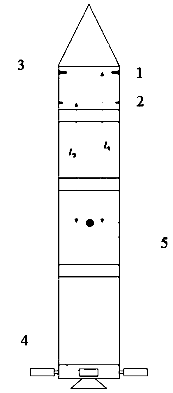
An attitude control and rocket technology, applied in the aerospace field, can solve the problems of complex control system, high procurement or self-research costs, restricting the commercial competitiveness of launch vehicles, etc., to simplify the control system and reduce costs.

Active Publication Date: 2020-08-11
BEIJING XINGJI RONGYAO SPACE TECH CO LTD +1
View PDF6 Cites 14 Cited by
  • Summary
  • Abstract
  • Description
  • Claims
  • Application Information

AI Technical Summary

Problems solved by technology

At this time, if the traditional control scheme continues to be used, the demand for the swing engine and its supporting servo mechanisms will be large, the cost of procurement or self-development will be high, and the control system will be complicated, which will restrict the commercial competitiveness of the launch vehicle.

Method used


Image

  • Rocket attitude control system
  • Rocket attitude control system
  • Rocket attitude control system

Examples


Embodiment Construction

[0026] The technical solutions of the present invention will be clearly and completely described below with reference to the accompanying drawings. Obviously, the described embodiments are a part of the embodiments of the present invention, but not all of the embodiments. Based on the embodiments of the present invention, all other embodiments obtained by those of ordinary skill in the art without creative efforts shall fall within the protection scope of the present invention.

[0027] In the description of the present invention, it should be noted that the terms "center", "upper", "lower", "left", "right", "vertical", "horizontal", "inner", "outer", etc. The indicated orientation or positional relationship is based on the orientation or positional relationship shown in the accompanying drawings, which is only for the convenience of describing the present invention and simplifying the description, rather than indicating or implying that the indicated device or element must hav...


PUM


Abstract

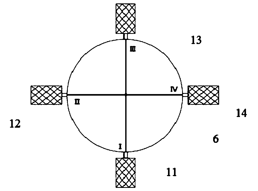
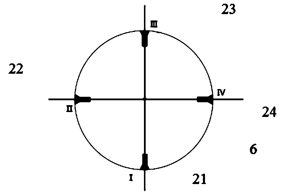
The invention discloses a rocket attitude control system. The system comprises grid rudders, first thrust attitude control spray pipes and second thrust attitude control spray pipes; the grid ruddersare distributed on the outer wall of the first-stage tail section of a rocket body; the first thrust attitude control spray pipes are distributed in a first mounting surface perpendicular to the longitudinal axis of the rocket body; the first mounting surface is close to the head of a rocket sub-stage; the second thrust attitude control spray pipes are distributed in a second mounting surface perpendicular to the longitudinal axis of the rocket body; and the second mounting surface is close to the tail of the rocket sub-stage; the thrust of the first thrust attitude control spray pipes is greater than that of the second thrust attitude control spray pipes. The grid rudders are arranged on the outer wall of the first-stage tail section of the rocket body; the uppermost stage of the rocket body is provided with the two kinds of attitude control spray pipes with different thrusts; and therefore, the control moment requirements of a rocket in different flight stages can be met, stable control over the whole-course flight of the rocket is achieved, and fixed engines can be in all the stages. Swing spray pipes and servo mechanisms of the swing spray pipes are omitted, and therefore, thecontrol system is simplified, and the cost of the carrier rocket is reduced.

Description

technical field [0001] The invention relates to the technical field of aerospace, in particular to a rocket attitude control system. Background technique [0002] For traditional launch vehicles, swing engines are usually configured at each stage as the main actuator, and nozzles are configured at the last stage as auxiliary actuators to achieve stable control of the rocket throughout the flight. Taking a four-stage rocket as an example, multiple sets of rocking engines (and their associated servo mechanisms) and final-stage nozzles are required in the control scheme. [0003] In recent years, with the rapid development of the commercial aerospace field, the importance of cost and economic benefits in the decision-making of launch vehicle development and production has increased rapidly. At this time, if the traditional control scheme is continued, the demand for the swing engine and its supporting servo mechanism is large, the procurement or self-research costs are high, a...

Claims


Application Information

Patent Timeline
IPC IPC(8): B64G1/24B64G1/26
CPCB64G1/244B64G1/26
Inventor 彭小波董彦民黄佩
Owner BEIJING XINGJI RONGYAO SPACE TECH CO LTD
Why Eureka
Eureka Blog
Learn More