
Tool and method for backfilling deep foundation pit excavation groove

A technology for deep foundation pits and fertilizer tanks, which is applied to earth movers/excavators, construction, etc., which can solve problems such as inconvenient transportation, long construction period, and difficulty in backfilling fertilizer tanks in deep foundation pits, and achieve the effect of convenient adjustment

Inactive Publication Date: 2020-08-11
CHINA CONSTR 4TH ENG BUREAU 6TH +1
View PDF6 Cites 2 Cited by
  • Summary
  • Abstract
  • Description
  • Claims
  • Application Information

AI Technical Summary

Problems solved by technology

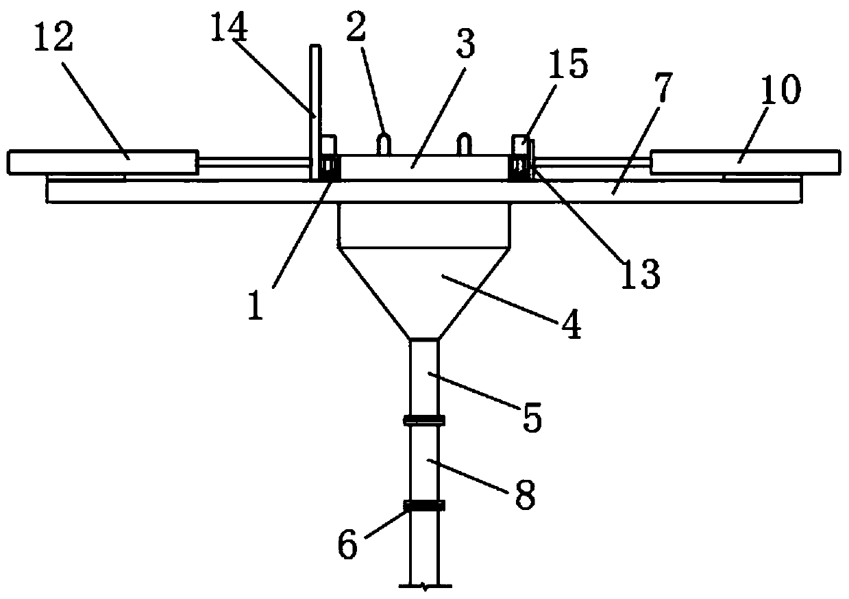
[0004] The object of the present invention is to provide a tool and method for backfilling the deep foundation pit fertilizer tank. The traditional funnel is applied to the project, and the backfill soil is backfilled into the deep foundation pit fertilizer tank by using the principle of the funnel, so as to solve the problem of deep foundation pit fertilizer. The problem of backfilling the groove is difficult. The tool is welded by stainless steel. According to the height of the backfill, multiple detachable cylinders can be installed. Flanges are used between the fixed cylinder, the detachable cylinder and the detachable cylinders. And bolted connection, each backfilling layer can be dismantled a section of detachable cylinder, which solves the technical problems of high cost and long construction period of traditional construction, which cannot guarantee the quality of the project and the safety of workers during operation;
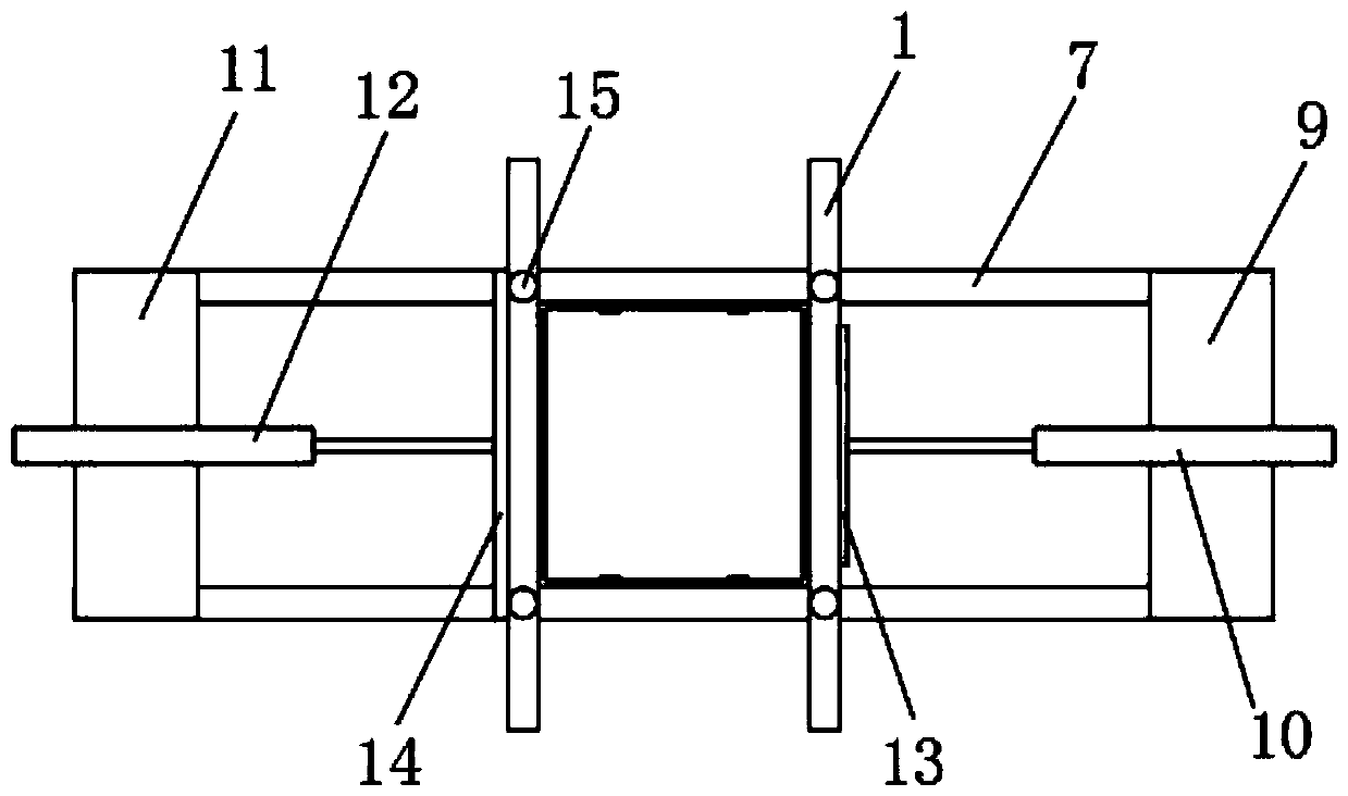
[0006] The present invention can install the fixed cylinder by opening the second through groove on the second baffle to match the fixed cylinder, and the first cylinder drives the first baffle to fix the funnel, so that the funnel can be stably placed on the On the support bar, it solves the technical problem that the traditional deep foundation pit fertilizer tank backfilling tools are not easy to transport

Method used


Image

  • Tool and method for backfilling deep foundation pit excavation groove
  • Tool and method for backfilling deep foundation pit excavation groove
  • Tool and method for backfilling deep foundation pit excavation groove

Examples


Embodiment Construction

[0032] The technical solutions of the present invention will be clearly and completely described below in conjunction with the embodiments. Apparently, the described embodiments are only some of the embodiments of the present invention, not all of them. Based on the embodiments of the present invention, all other embodiments obtained by persons of ordinary skill in the art without creative efforts fall within the protection scope of the present invention.

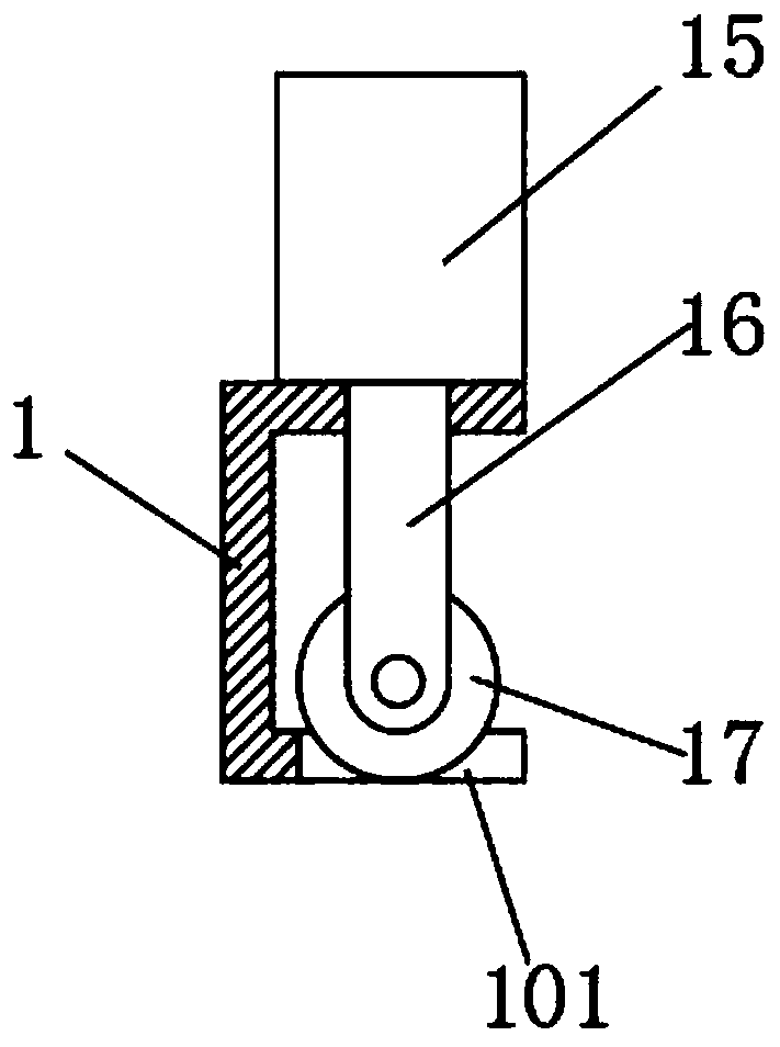
[0033] Such as Figure 1-5As shown, a tool for backfilling the fat groove of a deep foundation pit includes two fixed channel steels 1, the two fixed channel steels 1 are parallel to each other, and a funnel is arranged between the two fixed channel steels 1, and the funnels It includes a square bucket mouth 3 and a necking 4, the necking 4 is fixedly connected to the bottom of the square bucket mouth 3 by welding, and the middle parts of the two fixed channel steels 1 are respectively located on the tops of the two outer s...


PUM


Abstract

The invention discloses a tool and method for backfilling a deep foundation pit excavation groove. The tool comprises two fixed channel steel which are parallel to each other, and a funnel is arrangedbetween the two fixed channel steel. The funnel comprises a square hopper mouth and necking, a fixed cylinder is fixed to the bottom of the necking by welding, a flange is fixedly installed at the bottom of the fixed cylinder by welding, a plurality of detachable cylinders are arranged at the bottom of the fixed cylinder, and two supporting transverse bars are arranged below the fixed channel steel. A first cylinder is fixed to a first cylinder mounting plate, a first baffle is fixed to the end part of an output rod of the first cylinder, a second cylinder is fixed to a second cylinder mounting plate, and a second baffle is fixed to the end part of an output rod of the second cylinder. According to the tool and method for backfilling the deep foundation pit excavation groove, the cost issaved, the construction period is shortened, the quality of the project and the safety of workers during operation are ensured, safety and stability in the construction process are achieved, and the transportation of the excavation groove backfill tool is facilitated.

Description

technical field [0001] The invention relates to a tool and a method for backfilling soil, in particular to a tool and a method for backfilling a fertilizer groove in a deep foundation pit, and belongs to the technical field of backfilling tools and methods for building construction. Background technique [0002] In the construction of construction projects, deep foundation pit engineering is becoming more and more common. Most of the deep foundation pits use internal support plus enclosure piles and underground diaphragm walls as foundation pit support. Because most of the sites are in the city and the construction site is narrow, the distance between the retaining piles and the main body will be very small, which brings great difficulties to the backfill construction. The traditional method is to backfill a layer of plain soil for each layer of underground main body, carry out supporting concrete between the inner main body and the surrounding protection piles, and remove t...

Claims


Application Information

Patent Timeline
Patent Type & Authority Applications(China)
IPC IPC(8): E02F5/22
CPCE02F5/22
Inventor 王富瑶马一方钱鸿明葛虎闫宝玉金磊路野马凯程瑶孙丽乔勃
Owner CHINA CONSTR 4TH ENG BUREAU 6TH
Learn More