Method for sharing waterproof lamp shell by different optical systems

A technology for optical systems and lamps, which is applied in the direction of air-proof/waterproof devices, devices used in theaters and circuses, electric light sources, etc. It can solve the problems of moving the top lens of lamps, etc., and achieve the effect of saving product manufacturing costs

Inactive Publication Date: 2020-08-11
GUANGZHOU DASEN LIGHTING ELECTRONICS
View PDF1 Cites 0 Cited by
  • Summary
  • Abstract
  • Description
  • Claims
  • Application Information

AI Technical Summary

Problems solved by technology

[0004] The purpose of this invention is to provide a method for different optical systems to share a set of waterproof lamp shells, which is used to solve the problem of moving the top lens of the lamp when the optical system changes

Method used


Image

  • Method for sharing waterproof lamp shell by different optical systems
  • Method for sharing waterproof lamp shell by different optical systems
  • Method for sharing waterproof lamp shell by different optical systems

Examples


Embodiment 1

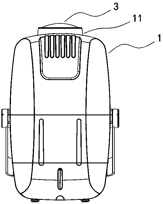
[0024] as attached figure 1 As shown, a method of sharing a set of waterproof lamp casings with different optical systems, the top of the waterproof lamp casing (1) includes an extension part (11) in the direction of light emission, and a light emission lens (3) is fixed on the extension part (11); when The optical system of this lamp becomes longer. If in order to change the lighting effect, the number of components of the original optical system needs to be increased or reduced, and the light-emitting lens (3) needs to be moved up to meet the new optical system, the existing waterproof lamp housing can be replaced. (1) Processing; the processing method is:

[0025] (1) Confirm whether the extension part (11) blocks light in the new optical system; if it blocks light, first process the extension part (11) to reduce the height of the extension part (11) to the state of not blocking light; if not If the light is blocked, proceed directly to step (2);

[0026] (2) According to...

Embodiment 2

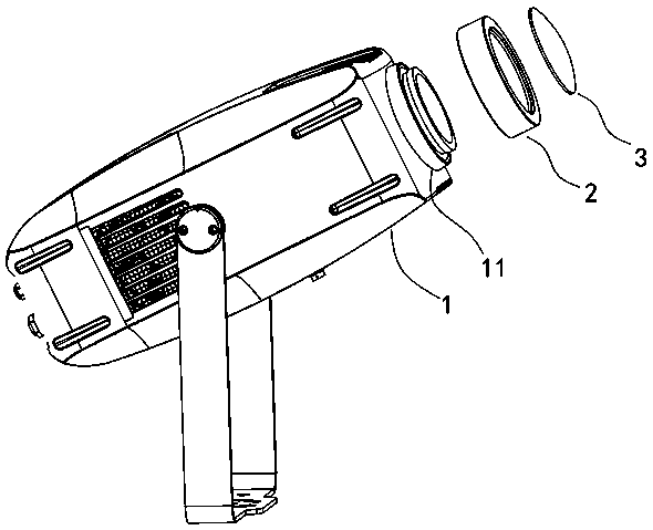
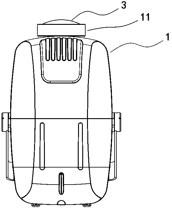
[0033] A method for sharing a set of waterproof lamp shells with different optical systems. The top of the waterproof lamp shell (1) includes an extension part (11) in the light emitting direction, and a light emitting lens (3) is fixed on the extension part (11); Initially, the waterproof lamp shell (1) was designed as a height-adjustable structure for the light-emitting lens (3). This design can avoid the need to increase or decrease the number of components of the original optical system in order to change the lighting effect, thereby changing the length of the optical system Sometimes, the original waterproof lighting shell cannot be shared, but a new mold must be opened. The height-adjustable design method of the light-emitting lens (3) is:

[0034] (1) The extension part (11) is designed as a hollow structure, and the outer wall of the extension part (11) is provided with screw teeth (12);

[0035] (2) Add a new lens cover (2), the inner wall of the lens cover (2) has s...


PUM


Abstract

Disclosed is a method for sharing a waterproof lamp shell by different optical systems. The top of the waterproof lamp shell comprises an extending part in the light emitting direction, and a light emitting lens is fixed to the extending part; the waterproof lamp shell is characterized in that when an existing waterproof lamp shell can meet a new optical system only by moving the light-emitting lens upwards, the existing waterproof lamp shell can be machined. A processing method comprises the following steps: (1) confirming whether the extending part in a new optical system blocks light or not; if the light is blocked, firstly processing the extension part, so that the height of the extending part is reduced to reach a non-light-blocking state; if light is not blocked, directly performingthe step (2); (2) adding a new lens cover according to the height of a light-emitting lens of a new optical system, and nesting the lens cover on the outer layer of the extending part; and fixing (3)the light-emitting lens in the new lens cover through dispensing, and nesting and fixing a lens cover and the extending part together through dispensing.

Description

technical field [0001] The invention belongs to the field of shells of stage or landscape lamps, in particular to the field of a method for sharing a set of waterproof lamp shells with different optical systems. Background technique [0002] In the actual manufacturing process of stage and landscape lighting manufacturers, because the cost of shell mold opening is relatively high, manufacturers often use one shell for multiple lamp types as much as possible out of cost considerations, thereby saving the cost of shell mold opening cost. [0003] Conventional mold opening methods usually limit the total stroke of the optical system of the lamp, that is, when the optical system of the lamp needs to add optical elements and the total optical stroke becomes longer or shorter, the original lens on the lens cover must be moved up accordingly. Or move down. At this time, because the size of the entire shell of the lamp is fixed, the position of the lens cannot be changed. Therefore...

Claims


Application Information

Patent Timeline
IPC IPC(8): F21S8/00F21V17/12F21V19/00F21V31/00F21W131/105F21W131/406
CPCF21S8/00F21V17/12F21V19/00F21V31/00F21W2131/105F21W2131/406
Inventor 许法卿向明勇
Owner GUANGZHOU DASEN LIGHTING ELECTRONICS
Why Eureka
Try Eureka