Improved partial endoprosthesis device for vertebral joint

A technology of prosthesis and equipment, applied in the field of local internal prosthesis equipment

Pending Publication Date: 2020-08-11
G&G公司 +2
View PDF11 Cites 2 Cited by
  • Summary
  • Abstract
  • Description
  • Claims
  • Application Information

AI Technical Summary

Problems solved by technology

Even if the device is provided with screws as the main stabilizing means, thus involving the above-mentioned disadvantages

Method used


Image

  • Improved partial endoprosthesis device for vertebral joint
  • Improved partial endoprosthesis device for vertebral joint
  • Improved partial endoprosthesis device for vertebral joint

Examples


Embodiment Construction

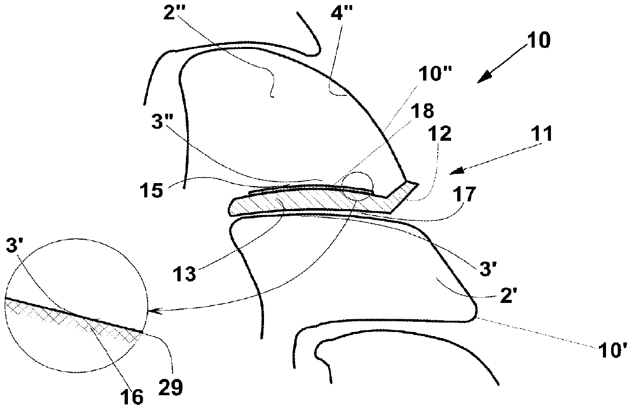
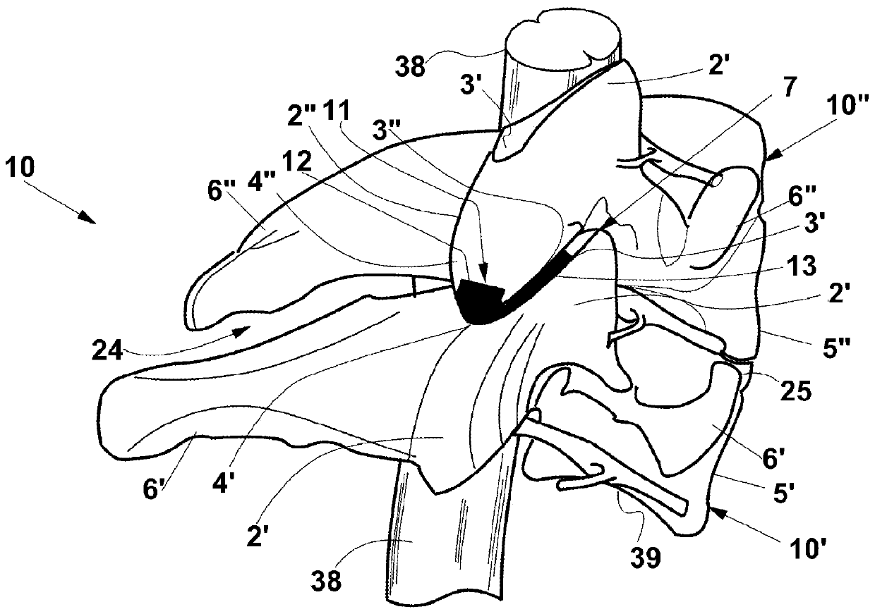
[0063] Exemplary embodiments of the local endoprosthetic device according to the present invention are described below. The device can be implanted in the joint space at or near the level of the neck. As shown in the figures, the device replaces the bony articular surface of one of two adjacent vertebrae, typically, but not limited to, the upper vertebrae, damaged, for example, by arthrosis. The present invention makes it possible to treat some vertebral diseases while maintaining the relative mobility of the adjacent vertebrae that define the joint space.

[0064] anatomy reference in figure 1 and figure 2 , which shows a spinal cord segment 10 comprising two lower vertebrae 10' and upper vertebral 10" adjacent cervical vertebrae. The vertebral bodies 5', 5 of the lower vertebral 10' and upper vertebral 10" are shown respectively ". Behind the vertebral bodies 5', 5", parts of the vertebral arches are shown, more specifically the lamina 4', 4", and their adjacent cervical...


PUM


Abstract

A partial endoprosthesis device (11) for preserving the motion of a vertebral joint for implant into a spinal segment (10) comprising an articular portion (13) being elongated along a longitudinal axis (14) with a first face (15) and a second face (17) opposite to the first face (15), the first face comprising a central protrusion (18) having a height (H), with respect to the face, and a surface (16) of an osteointegrable material. The protrusion is configured so that, by implanting the device (11) with the articular portion (13) inserted between an upper articular facet (3') of a lower vertebra (10') and a corresponding lower articular facet (3'') of upper vertebra (10") adjacent to the lower vertebra, and with the first face (15) in contact with a first articular facet selected between the upper articular facet (3') and the lower articular facet (3''), and with the second face (17) in contact with a second articular facet respectively with the lower articular facet (3'') and with theupper articular facet (3'), it is obtained that the articular portion (13), with the first face (15), pushes against the first articular facet and finally becomes integral by osteointegration with the lower articular facet (3'') and, with the second face (17), slidingly engages with the lower articular facet (3').

Description

technical field [0001] The present invention relates to a partial endoprosthetic device for intervertebral joints. [0002] The device is indicated for the treatment of patients suffering from early facet or disc degeneration with incipient foraminal stenosis while maintaining the relative motion of the two adjacent vertebrae. Background technique [0003] It is well known that most spinal pain conditions are caused by the state of the joints, ie, they depend on relative motion deficits of the joint facets. This is especially true for most neck pains. [0004] Existing devices for the treatment of these spinal pain conditions can be divided simply into fusion devices for two or more adjacent vertebrae to inhibit their relative motion and, on the other hand, devices for maintaining relative motion. Typically, the devices used to maintain relative motion are interbody devices, more specifically they contain disc replacement elements. In fact, only interbody devices exist fo...

Claims


Application Information

Patent Timeline
Patent Type & Authority Applications(China)
IPC IPC(8): A61B17/70A61F2/44
CPCA61F2/4405A61B17/7064A61F2002/30168A61F2002/30224A61F2002/30235A61F2002/30879A61F2002/3093A61F2002/0081A61F2002/30774A61F2310/00023
Inventor G·因诺森齐P·彼得里尼G·古伊扎蒂
Owner G&G公司
Why Eureka
Try Eureka